
Wide-area site-based video surveillance system

a video surveillance and site-based technology, applied in the field of surveillance systems, can solve problems such as the inability of conventional individual camera systems to detect threats, and the inability of conventional systems to detect threats

Inactive Publication Date: 2008-11-27
OBJECTVIDEO
View PDF15 Cites 62 Cited by
  • Summary
  • Abstract
  • Description
  • Claims
  • Application Information

AI Technical Summary

Benefits of technology

[0009]An embodiment of the invention may be a computer-readable medium contains software that, when read by a computer, causes the computer to perform a method for wide-area site-based surveillance. The method includes receiving surveillance data, including view targets, from a plurality of sensors at a site; synchronizing the surveillance data to a single time source; maintaining a site model of the site, wherein the site model comprises a site map, a human size map, and a sensor network model; analyzing the synchronized data using the site model to determine if the view targets re

Problems solved by technology

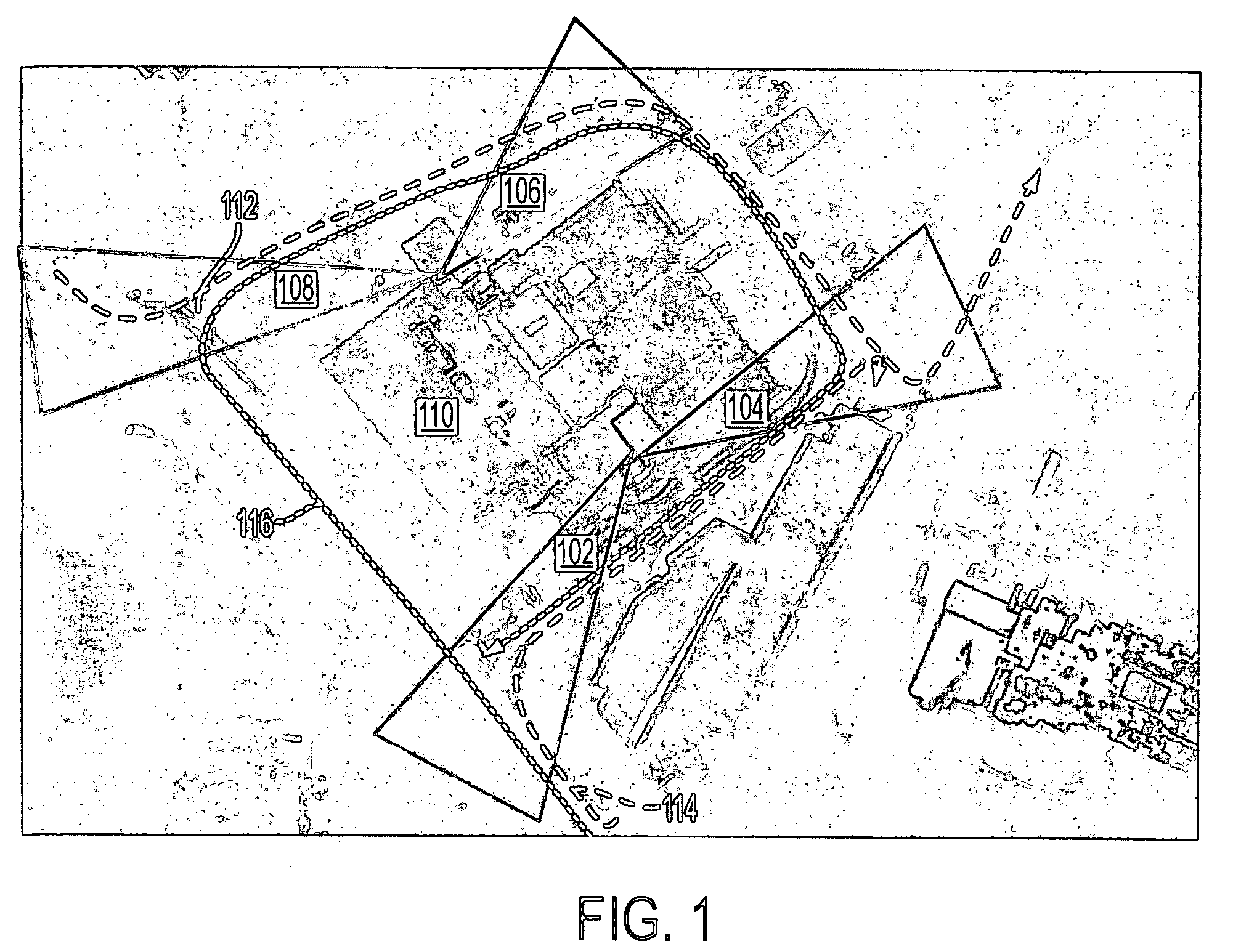
While this type of system has been proven to be very effective and helpful for video surveillance applications, its capability may be constrained by the fact that an isolated single camera can only monitor a limited area.
Further, conventional systems usually do not remember past targets, especially when the past targets appeared to act normally, thus a conventional system cannot detect the threats which can only be inferred by repeatable actions.
The conventional individual camera system would fail to detect the threats because a target of interest may loiter at the site for more than an hour, but not stay in any single camera view for more than two minutes, or the same suspect target might approach the site five times in a day but from different directions.

Method used


Image

  • Wide-area site-based video surveillance system
  • Wide-area site-based video surveillance system
  • Wide-area site-based video surveillance system

Examples


Embodiment Construction

[0054]An exemplary embodiment of the invention may be discussed in detail below. While specific exemplary embodiments may be discussed, it should be understood that this may be done for illustration purposes only. A person skilled in the relevant art will recognize that other components and configurations can be used without parting from the spirit and scope of the invention.

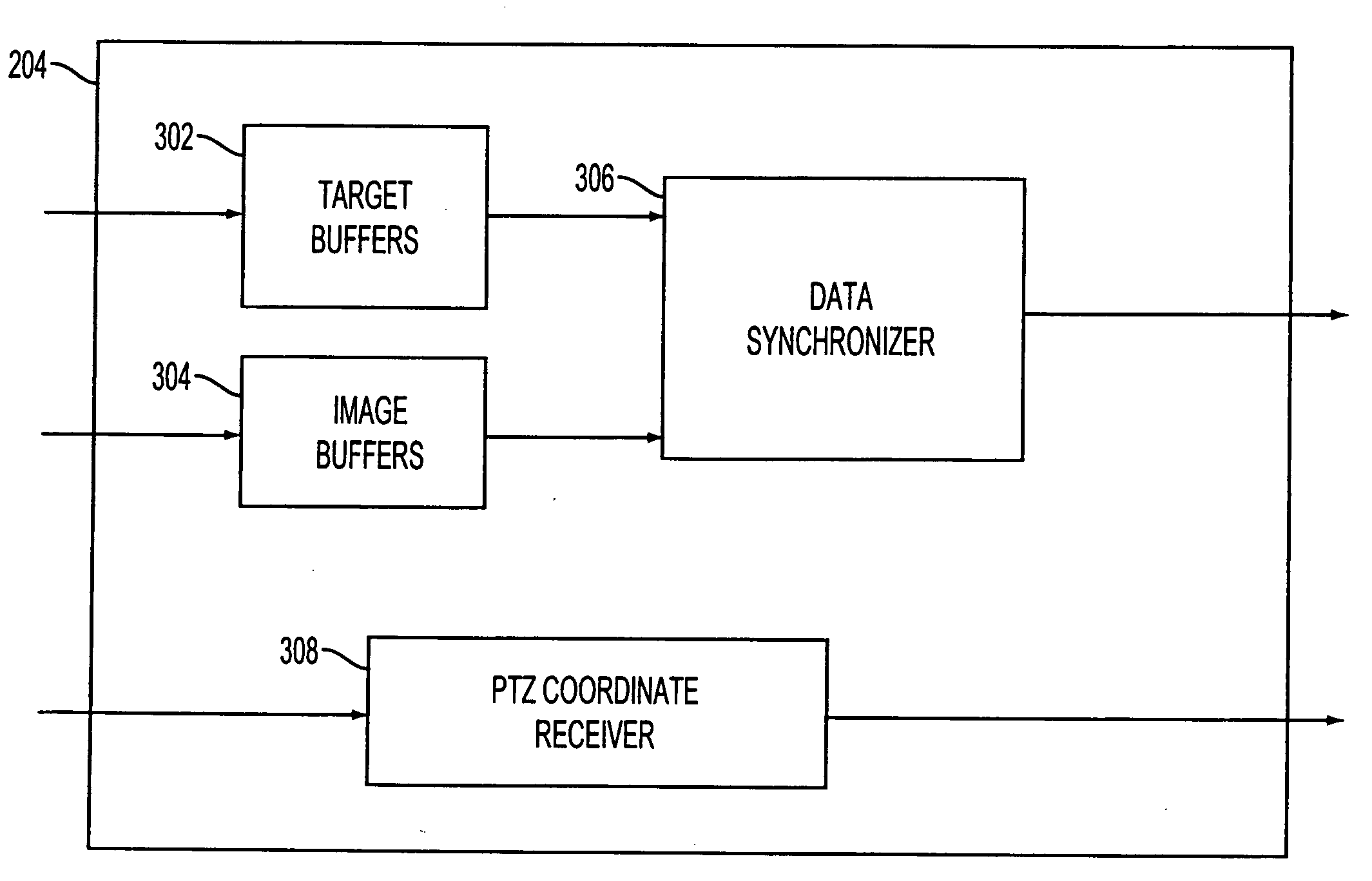
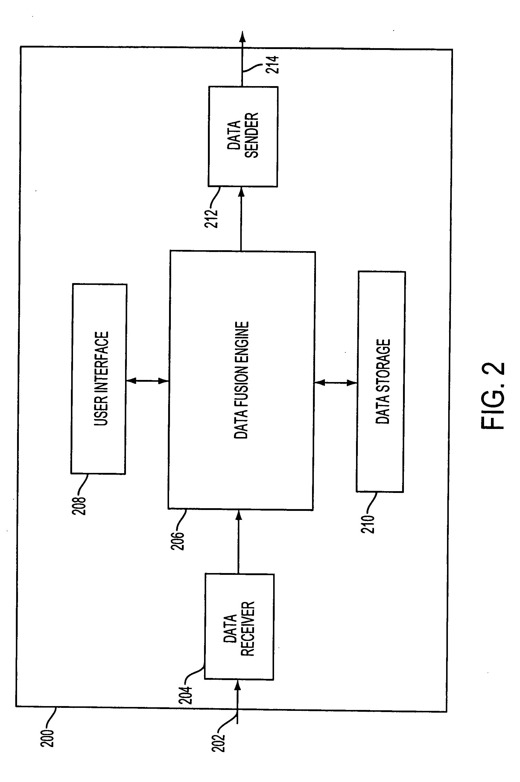
[0055]Embodiments of the present invention may be based on existing single camera IVS systems with increased automatic situation awareness capability under both spatial and temporal domains. The input to the system may be content analysis results from multiple individual cameras, such as tracked humans and vehicles. The output may be tracked targets in the site under monitoring and global events detected by the system. In summary, the task of the system may be to perform data fusion on the information from individual sensors and provide more reliable and powerful surveillance capability.

[0056]There may be severa...


PUM


Abstract

A computer-readable medium contains software that, when read by a computer, causes the computer to perform a method for wide-area site-based surveillance. The method includes receiving surveillance data, including view targets, from a plurality of sensors at a site; synchronizing the surveillance data to a single time source; maintaining a site model of the site, wherein the site model comprises a site map, a human size map, and a sensor network model; analyzing the synchronized data using the site model to determine if the view targets represent a same physical object in the site; creating a map target corresponding to a physical object in the site, wherein the map target includes at least one view target; receiving a user-defined global event of interest, wherein the user-defined global event of interest is based on the site map and based on a set of rules; detecting the user-defined global event of interest in real time based on a behavior of the map target; and responding to the detected event of interest according to a user-defined response to the user-defined global event of interest.

Description

RELATED APPLICATIONS[0001]This application is a continuation-in-part, and claims the benefit, of U.S. application Ser. No. 11 / 098,579, filed Apr. 5, 2005, of common assignee, entitled “Wide-Area Site-Based Video Surveillance System,” the contents of which are incorporated by reference in their entirety.BACKGROUND OF THE INVENTION[0002]1. Field of the Invention[0003]This invention relates to surveillance systems. Specifically, the invention relates to a video-based surveillance system that monitors a wide range of area by fusing the data from multiple surveillance cameras.[0004]2. Related Art[0005]Some state of art intelligent video surveillance (IVS) system can perform content analysis on the image view of each camera. Based on user defined rules or policies, IVS systems can automatically detect potential threats by detecting, tracking and analyzing the targets in the scene. While this type of system has been proven to be very effective and helpful for video surveillance application...

Claims


Application Information

Patent Timeline
IPC IPC(8): H04N7/18G06V10/24
CPCG06K9/00771G06K9/32G06K9/3216G08B13/19613G08B13/19641G08B13/19645H04N5/76H04N5/781H04N5/85H04N5/907H04N7/181G06V20/52G06V10/24G06V10/245
Inventor ZHANG, ZHONGYU, LILIU, HAIYINGBREWER, PAULCHOSAK, ANDREWGUPTA, HIMAANSHUHAERING, NIELSJAVED, OMARLIPTON, ALAN J.RASHEED, ZEESHANSCANLON, W. ANDREWTITUS, STEVEVENETIANER, PETERYIN, WEIHONGYU, LIANGYIN
Owner OBJECTVIDEO
Learn More