
Micropower neural amplifier with adaptive input-referred noise

a neural amplifier and input-referred noise technology, applied in the field of ultralow-power neural recording amplifiers, can solve the problems of limiting the power efficiency of the multi-electrode system, the power required for the neural amplifier can become the limiting factor of the whole multi-electrode system, and the power required for the neural amplifier can become the limiting factor of the whole system, etc., to achieve low noise gain, low noise gain, low noise gain

Active Publication Date: 2008-11-27
MASSACHUSETTS INST OF TECH
View PDF4 Cites 25 Cited by
  • Summary
  • Abstract
  • Description
  • Claims
  • Application Information

AI Technical Summary

Benefits of technology

[0007]According to one aspect of the invention, there is provided a micropower neural amplifier with adaptive power biasing for use in multi-electrode arrays. The micropower neural amplifier includes a low noise gain stage, the low noise gain stage implemented using an amplifier and pseudoresistor elements. A band pass filter stage shapes a pass band of the amplifier.
[0008]According to another aspect of the invention, there is provided a micropower neural amplifier with adaptive power biasing for use in multi-electrode arrays. The micropower neural amplifier includes a low noise gain stage. The low noise gain stage is implemented using an amplifier and pseudoresistor elements. The MOS-bipolar pseudoresistor element's noise being in the low frequencies, thereby allowing the low frequency noise to be filtered prior to pass band and does not appear in a frequency of interest. A band pass filter stage shapes a pass band of the amplifier.
[0009]According to another aspect of the invention, there is provided a micropower neural amplifier with adaptive power biasing for use in multi-electrode arrays. The micropower neural amplifier includes a low noise gain stage. The low noise gain stage is implemented using an amplifier and pseudoresistor elements. The amplifier is implemented using a modified version of a standard folded-cascode topology. The modification

Problems solved by technology

This relationship shows the steep power cost of achieving low-noise performance in an amplifier.
If such amplifiers are to be used in a multi-electrode array, with a power near 100 μW per amplifier for most designs, the power required for the neural amplifiers can become the limiting factor for the whole multi-electrode system.
Even though the latter design achieves a power-noise tradeoff near theoretical limit of its particular OTA topology, the topology used is not power-efficient since a large portion of the current in it is wasted in its current mirrors.

Method used


Image

  • Micropower neural amplifier with adaptive input-referred noise
  • Micropower neural amplifier with adaptive input-referred noise
  • Micropower neural amplifier with adaptive input-referred noise

Examples


Embodiment Construction

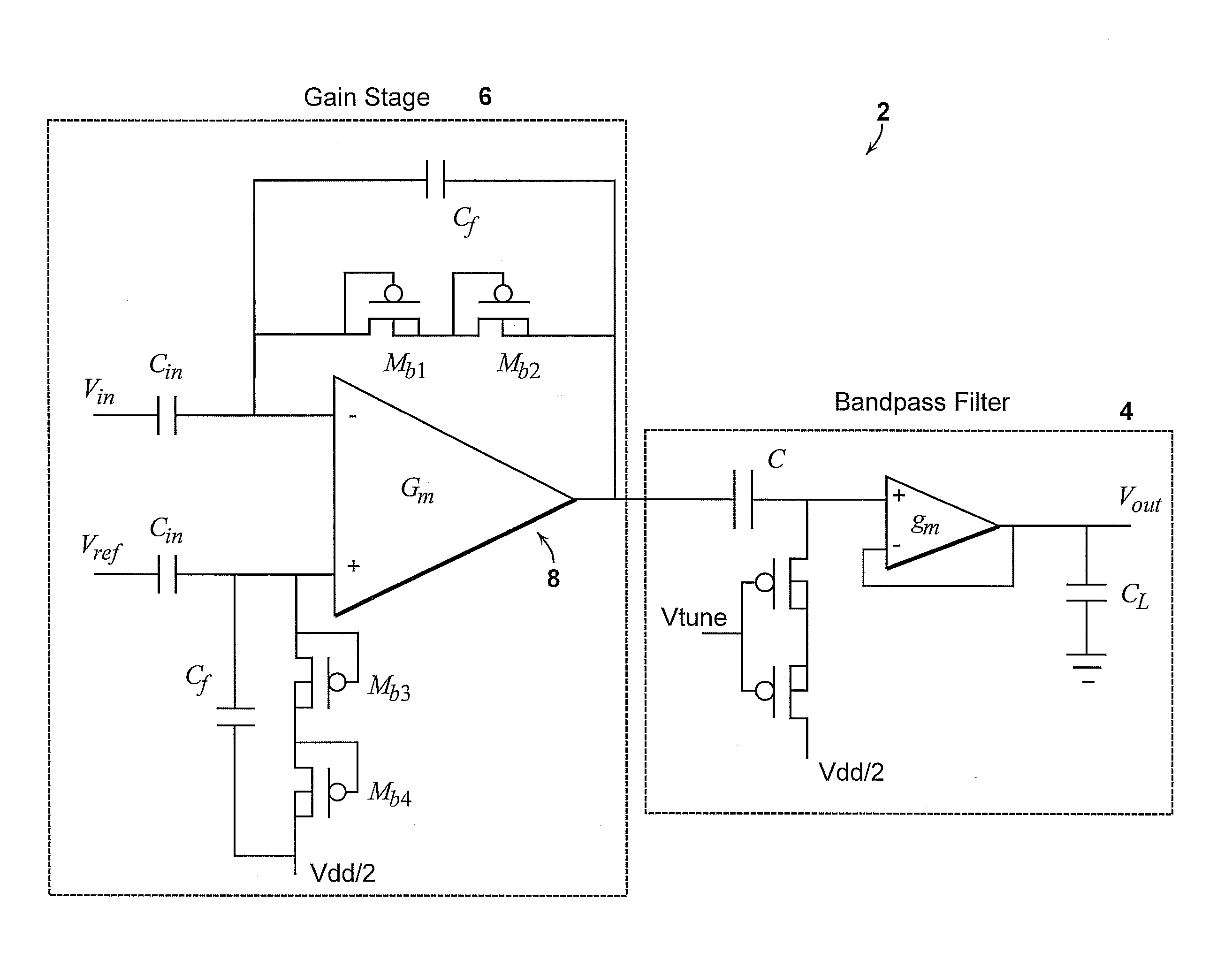
[0027]The invention involves an ultra-low-power neural recording amplifier. The amplifier appears to be the lowest power and most energy-efficient neural recording amplifier reported to date. Low-noise design techniques are used that help the neural amplifier achieve input-referred noise that is near the theoretical limit of any amplifier using a differential pair as an input stage.

[0028]The overall schematic of a neural amplifier 2 is shown in FIG. 1. The neural amplifier 2 includes a bandpass filter stage following a gain stage 6 to shape the passband of the amplifier 2. The low-frequency high-pass cutoff of the gain stage 6 is created by the MOS-bipolar pseudoresistor element formed by Mb1-Mb2 and the capacitance Cf. The capacitive feedback formed by Cf and Cin sets the midband gain of the amplifier 2 to approximately 40.8 dB. The high-pass cutoff and the low-pass cutoff frequencies of the amplifier 2 can be adjusted via Vtune and the bias current of the gm-OTA in a bandpass-filt...


PUM


Abstract

A micropower neural amplifier with adaptive power biasing for use in multi-electrode arrays is provided. The micropower neural amplifier includes a low noise gain stage. The low noise gain stage is implemented using an amplifier and pseudoresistor elements.

Description

PRIORITY INFORMATION[0001]This application claims priority from provisional application Ser. No. 60 / 940,105 filed May 25, 2007, which is incorporated herein by reference in its entirety.BACKGROUND OF THE INVENTION[0002]The invention relates to the field of neural recording amplifier, and in particular to an ultra-low-power neural recording amplifier.[0003]Large-scale chronic multi-electrode neural-recording systems are being built to enable us to understand how the brain works. With the help of such systems, a number of experiments have shown that it is possible to predict intended limb movements by simultaneously recording from many neurons, and interpreting their cortical activities. For example, brain-machine interfaces are being built to help a paralyzed patient move a computer cursor by thoughts alone. Portable, chronic use of such interfaces may eventually play an important role in treatment of paralyzed patients, and enable large-scale monitoring of the brain in experimental ...

Claims


Application Information

Patent Timeline
IPC IPC(8): H03F3/45
CPCH03F1/0266H03F1/26H03F3/45192
Inventor SARPESHKAR, RAHULRAPOPORT, BENJAMIN I.WATTANAPANITCH, WORADORN
Owner MASSACHUSETTS INST OF TECH
Learn More