
Device for irrigating and inspecting a wound

a technology for irrigating and inspecting wounds, applied in medical science, surgery, diagnostics, etc., can solve the problems of rapid bacterial build-up and consequent infection, inability to irrigate wounds, so as to reduce lens distortion

Inactive Publication Date: 2008-11-20
FOSTER KEVIN L
View PDF9 Cites 1 Cited by
  • Summary
  • Abstract
  • Description
  • Claims
  • Application Information

AI Technical Summary

Benefits of technology

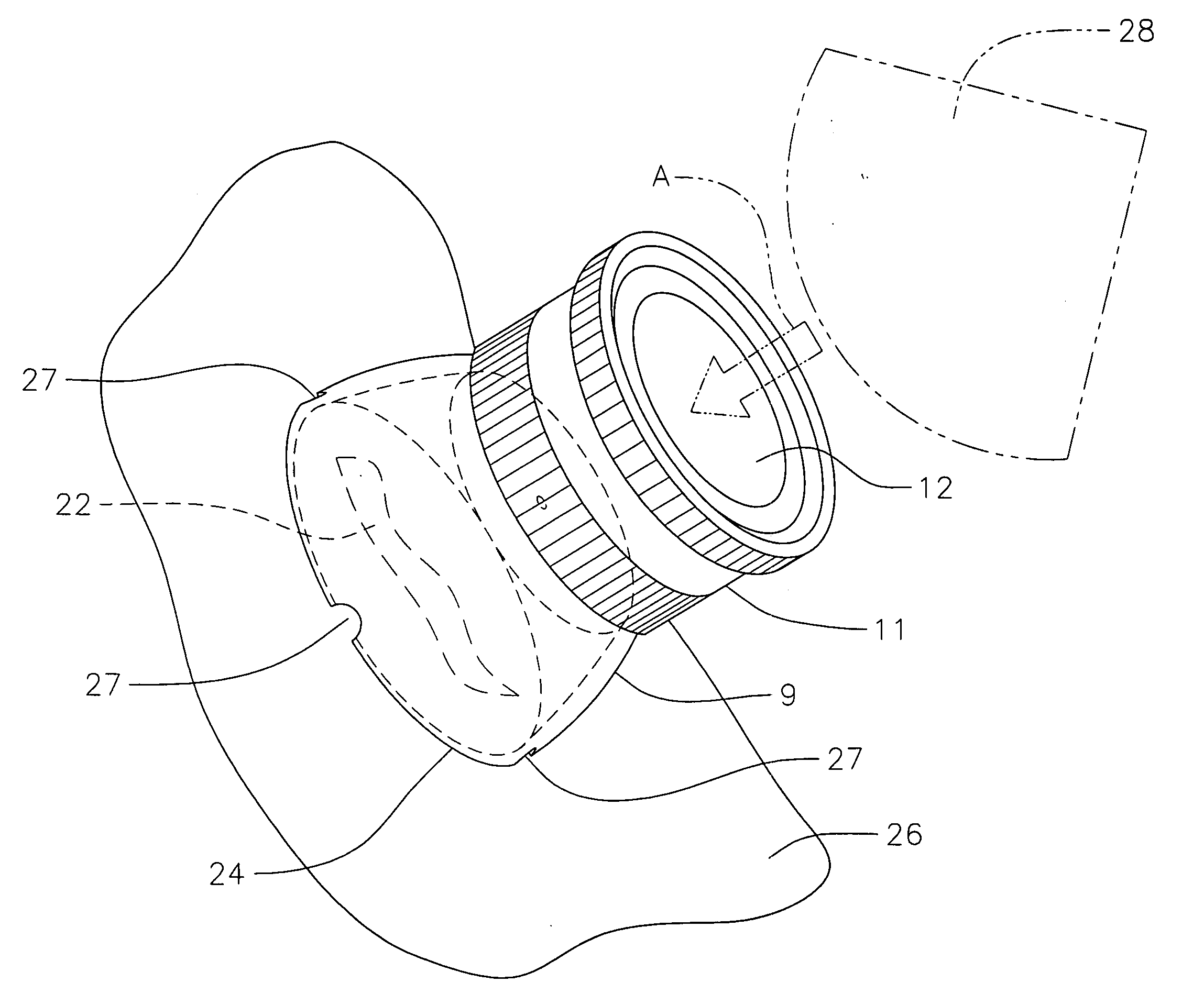
[0006]To permit magnification of the open wound, a magnifying lens is carried by the coupling member intermediate the upstream end portion and the downstream end portion where the upstream surface of the lens forms a downstream boundary of the void region and the downstream surface of the lens forms an upstream boundary of the chamber region located within the downstream end portion of the coupling member. The magnifying lens has a multiplicity of orifices radially spaced adjacent the peripheral edge of said lens to minimize lens distortion and to permit the cleansing fluid to flow from the void region to the chamber region upon sufficient compression of the container.

Problems solved by technology

Open wounds or lacerations generally contain contaminants and debris that unless timely removed will cause the wound to become infected.
The presence of residual contaminants or debris may be the source of bacterial build-up and consequent infection even after the wound has been irrigated with a cleansing solution.
If no contaminants are seen the wound is considered cleansed and irrigation is discontinued; the presence, however, of contaminants or debris that was undetected by visual inspection may be a source for a rapid bacterial build-up and consequent infection.

Method used


Image

  • Device for irrigating and inspecting a wound
  • Device for irrigating and inspecting a wound
  • Device for irrigating and inspecting a wound

Examples


Embodiment Construction

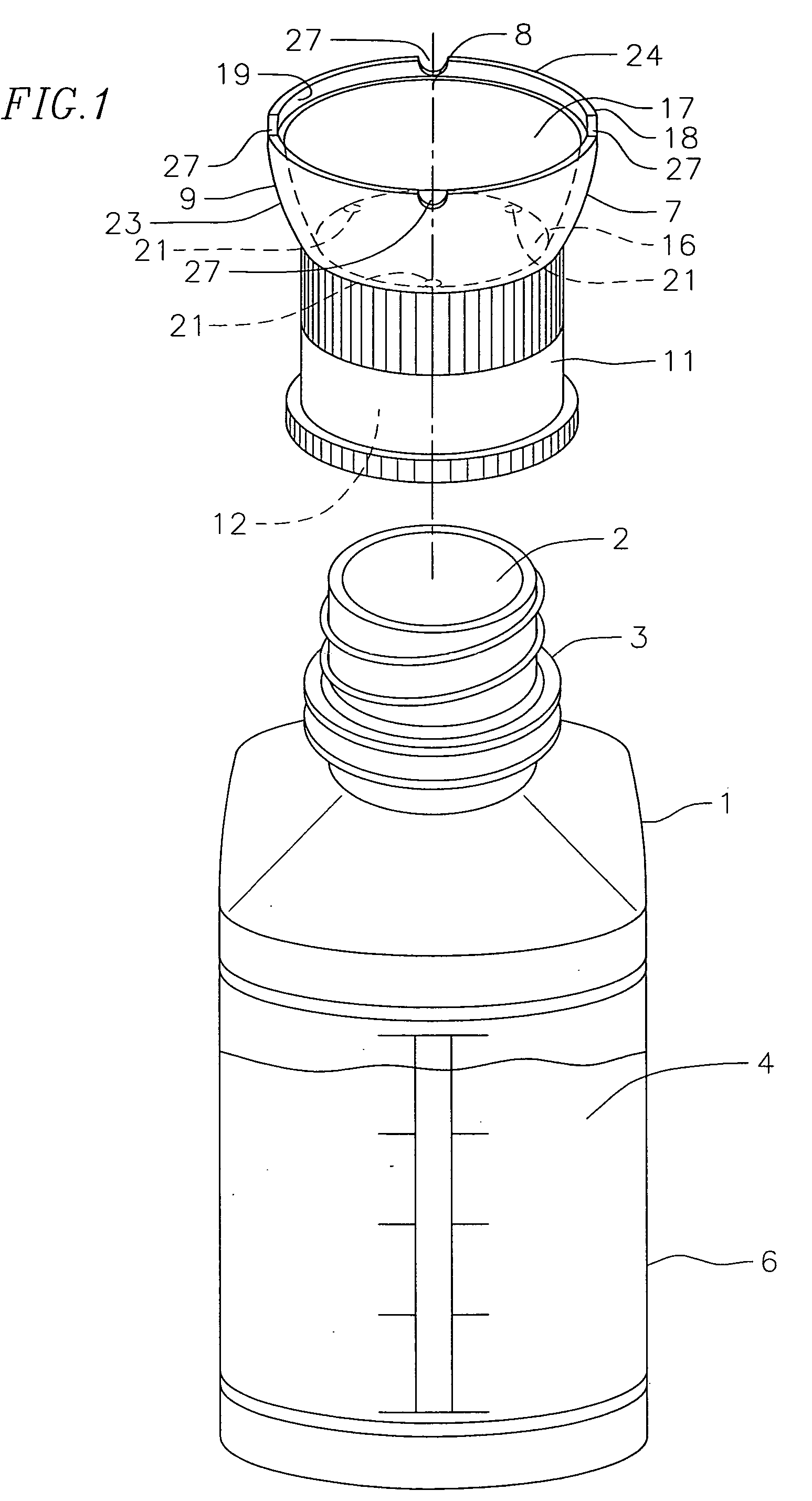
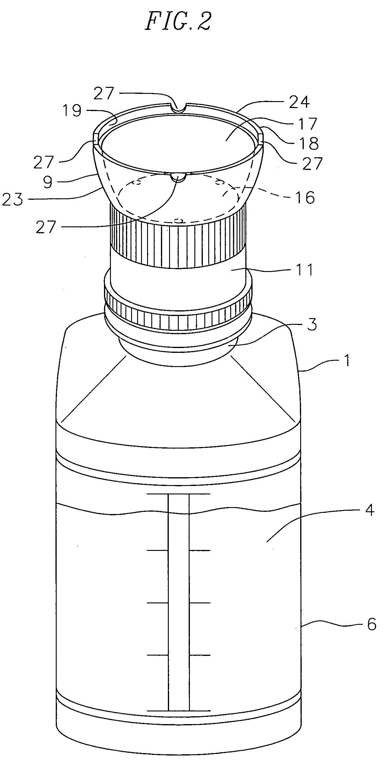
[0018]FIG. 1 is a perspective view illustrating the cleansing fluid container 1 having a dispensing outlet 2 and a neck portion 3 where neck portion 3 ordinarily is threaded or otherwise adapted for closure by a cap (not shown) that seals the outlet and is removed when the cleansing fluid 4 is to be dispensed. Container 1 is commonly made of a resilient plastic material and the cleansing fluid 4 is generally a saline type solution. As can further be seen in FIG. 1, container 1 has a reservoir region 6 which retains the cleansing fluid 4. In order to dispense the cleansing fluid from the reservoir, other than by gravity, container 1 is resiliently constructed and manually compressible such that the cleansing fluid is dispensed under pressure from the reservoir through dispensing outlet 2.

[0019]Referring to FIG. 1, coupling member 7 of this invention is shown in perspective and in explosive association axially removed from container 1. Although not shown in FIG. 1, but can be seen in ...


PUM


Abstract

The invention relates to a device for more effectively performing wound irrigation and cleansing. The device consists of a coupling member that may be releasably coupled by threaded engagement with the dispensing outlet of a manually compressible container having a reservoir of cleansing fluid. The coupling member has an upstream end portion containing a void region which is in fluid communication with the reservoir after coupling. A magnifying lens is carried by the coupling member and is located intermediate the upstream and downstream ends of the coupling member. The magnifying lens has a multiplicity of orifices adjacent its peripheral edge where the orifices communicate with both the void region and a chamber region. The chamber region is located downstream of the lens and has an opening at its downstream end to permit cleansing fluid to be delivered to the wound upon manually compressing the container. After cleansing the wound, the coupling member is de-coupled from the container and the wound inspected through the magnifying lens for contaminants or debris.

Description

[0001]This is a continuation-in-part application of application Ser. No. 11 / 804,116 filed May 17, 2007.FIELD OF THE INVENTION [0002]This invention relates to a device for more effectively performing wound irrigation and cleansing of contaminants by utilizing a magnification lens.BACKGROUND OF THE INVENTION [0003]Open wounds or lacerations generally contain contaminants and debris that unless timely removed will cause the wound to become infected. The presence of residual contaminants or debris may be the source of bacterial build-up and consequent infection even after the wound has been irrigated with a cleansing solution. The most common procedure for cleansing wounds is by irrigation methods well known in the prior art such as those described in the U.S. Pat. No. 6,468,253 and U.S. Pat. No. 4,769,003. The discharge nozzles, bulb type syringes, and gravity flow devices of the prior art rely upon a steady volumetric stream of cleansing fluid during the irrigation process to wash the...

Claims


Application Information

Patent Timeline
IPC IPC(8): A61M35/00A61B5/00
CPCA61M3/0262A61M3/0287A61M35/003A61M2205/583
Inventor FOSTER, KEVIN L.
Owner FOSTER KEVIN L
Learn More