
System and method for improving the resolution of an optical fiber gyroscope and a ring laser gyroscope

a technology of optical fiber gyroscope and laser gyroscope, which is applied in the direction of speed measurement using gyroscopic effects, instruments, surveying and navigation, etc. it can solve the problems of interference pattern beating at the detector, slow rotation rate, and large size of the entire unit, so as to improve the resolution of the optical fiber gyroscope

Inactive Publication Date: 2008-11-20
FULLERTON LARRY W
View PDF2 Cites 8 Cited by
  • Summary
  • Abstract
  • Description
  • Claims
  • Application Information

AI Technical Summary

Benefits of technology

[0011]Briefly, the present invention is an improved system and method for improving the resolution of an optical fiber gyroscope and a ring laser gyroscope. One aspect of the invention involves a method for determining the angular velocity of a platform relative to a gyroscope including the steps of producing a plurality of entangled particles at a source, introducing the plurality of entangled particles into an interferometer, detecting an interference pattern using one or more detectors, and determining the angular velocity of the platform based upon the interference pattern. The interference pattern may be a temporal interference pattern or a spatial interference pattern. The method may further include the steps of splitting the plurality of entangled particles into a first portion of entangled particles and a second portion of entangled particles, and directing the first portion of entangled particles and the second portion of entangled particles to follow a trajectory in opposite directions.

Problems solved by technology

Additionally, the entire unit is compact, lightweight and virtually indestructible, meaning it can be used in aircraft.
As the apparatus rotates, light in one branch travels a different distance than the other branch, changing its phase and resonance frequency with respect to the light travelling in the other direction, resulting in the interference pattern beating at the detector.
RLGs, while more accurate than mechanical gyros, suffer from an effect known as “lock-in” at very slow rotation rates.
At this low rotation, the nulls in the standing wave tend to “get stuck” on the mirrors, locking the frequency of each beam to the same value, and the interference fringes no longer move relative to the detector; in this scenario, the device will not accurately track its angular position over time.
The resulting phase shift affects how the beams interfere with each other when they are combined.
The FOG typically shows a higher resolution than a RLG but also a higher drift and worse scale factor performance.

Method used


Image

  • System and method for improving the resolution of an optical fiber gyroscope and a ring laser gyroscope
  • System and method for improving the resolution of an optical fiber gyroscope and a ring laser gyroscope
  • System and method for improving the resolution of an optical fiber gyroscope and a ring laser gyroscope

Examples


Embodiment Construction

[0032]The present invention will now be described more fully in detail with reference to the accompanying drawings, in which the preferred embodiments of the invention are shown. This invention should not, however, be construed as limited to the embodiments set forth herein; rather, they are provided so that this disclosure will be thorough and complete and will fully convey the scope of the invention to those skilled in the art. Like numbers refer to like elements throughout.

[0033]The present invention provides a system and method for improving the resolution of an optical fiber gyroscope and a ring laser gyroscope.

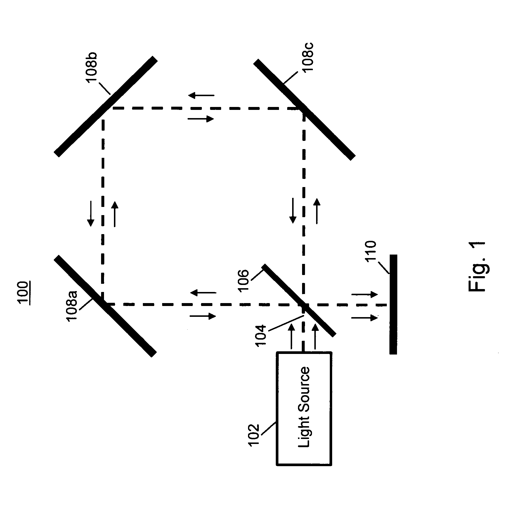
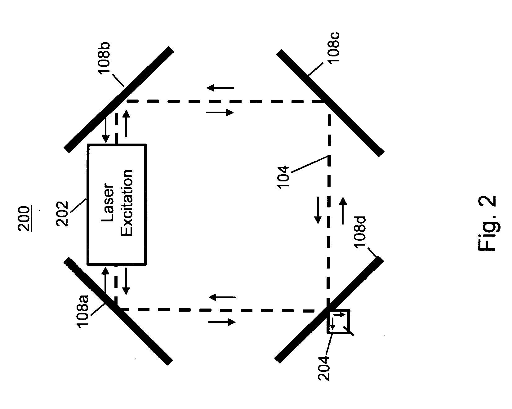
[0034]FIG. 1 illustrates an exemplary Sagnac interferometer 100. Referring to FIG. 1, a Sagnac interferometer includes a light source 102 that produces a beam of light 104. Half of the beam of light 104 reflects off a beam splitter (e.g., halfsilvered mirror) 106 and travels in one direction reflecting off of a first mirror 108a, a second mirror 108b, and a third mirror ...


PUM


Abstract

A system and method for improving the resolution of an optical fiber gyroscope and a ring laser gyroscope is provided. Entangled photons are introduced into an interferometer of a gyroscope. One or more detectors detect an interference pattern used to determine the angular velocity of a platform. The interference pattern may be a spatial and / or temporal interference pattern. The detectors may count the sub-wavelength interferometer fringes that indicate the direction and degree of angular rotation about the central axis of the apparatus. The detectors may measure a beat frequency.

Description

CROSS-REFERENCE TO RELATED APPLICATIONS [0001]This U.S. Non-Provisional Patent Application claims priority to U.S. Provisional Patent Application No. 60 / 930,161, filed May 14, 2007, which is incorporated herein by reference in its entirety.FIELD OF THE INVENTION [0002]The present invention relates generally to a system and method for improving the resolution of an optical fiber gyroscope and a ring laser gyroscope. More particularly, the present invention relates to using entangled photons to realize more precise measurements in an optical fiber gyroscope and a ring laser gyroscope.BACKGROUND OF THE INVENTION [0003]It is desirable to have an improved system and method for improving the resolution of an optical fiber gyroscope and a ring laser gyroscope.[0004]As described by Wikipedia, a gyroscope (or gyro) is a device for measuring or maintaining the orientation of an object. Gyroscopes can be used to construct gyrocompasses which complement or replace magnetic compasses, to assist ...

Claims


Application Information

Patent Timeline
Patent Type & Authority Applications(United States)
IPC IPC(8): G01C19/64
CPCG01C19/64
Inventor FULLERTON, LARRY W.
Owner FULLERTON LARRY W
Learn More