Eureka AIR delivers breakthrough ideas for toughest innovation challenges, trusted by R&D personnel around the world.

Helicopter Rotor Control System with Individual Blade Control

Active Publication Date: 2008-11-13
AIRBUS HELICOPTERS TECH GMBH
View PDF3 Cites 44 Cited by
  • Summary
  • Abstract
  • Description
  • Claims
  • Application Information

AI Technical Summary

Benefits of technology

[0007]The present invention is directed to a method and apparatus for controlling the pitch of individual rotor blades of a helicopter to reduce any or all of control loads imposed on the rotating rotor control elements, vibration in the rotating or non-rotating elements of the helicopter, and reducing noise generated by the rotating rotor blades.

Problems solved by technology

Common problem in the control and operation of rotary wing aircraft, such as helicopters, is in the control of the pitch of the rotor blades as the rotor rotate to provide lift and control to the helicopter.
As is well known, the lift and control provided by the rotor blades is generally achieved by altering the pitch of the rotor blades as the blades rotate, which in turn results in rapidly changing dynamic loads on the blades during rotation, due in part to the dynamic forces induced due to the changing pitches of the blades and in part due to aerodynamic forces acting on the blades.
These problems are compounded by dynamic forces, such as vibration, from the helicopter power and drive trains and aerodynamic forces acting on the body and other surfaces of the helicopter.
These problems, in turn, result in yet other problems, such as excessive noise generated by the rotors, increased power consumption, increased control loads on the helicopter control systems, including the pilot, and increased vibration and stresses on the entire rotor and power system and the components thereof and on the structural components of the aircraft.
This approach, however, does not address the sources of vibration and other unwanted physical effects resulting from the rotor blades as individual elements in dynamic motion around the rotation path.
While advantageous in some respects, these approaches again do not address the effects of vibration and other unwanted physical effects resulting from the rotor blades as individual elements in dynamic motion around the rotation path.
These methods instead essentially attempt to dissipate the vibration in the structure or materials of the blades and the drive train, which shifts the end result of the problem but which does not address the adverse results in terms of such matters as, for example, excessive wear of the rotor, drive train and structural components, fuel consumption and control system load.
In fact, these approaches may worsen the problems in some respects by substituting a quieter rotor material for a more durable rotor material.

Method used


Image

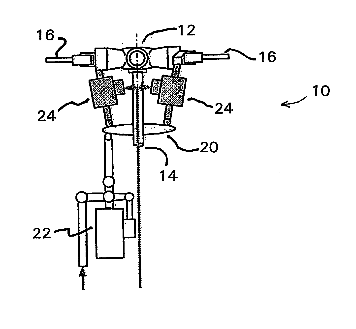
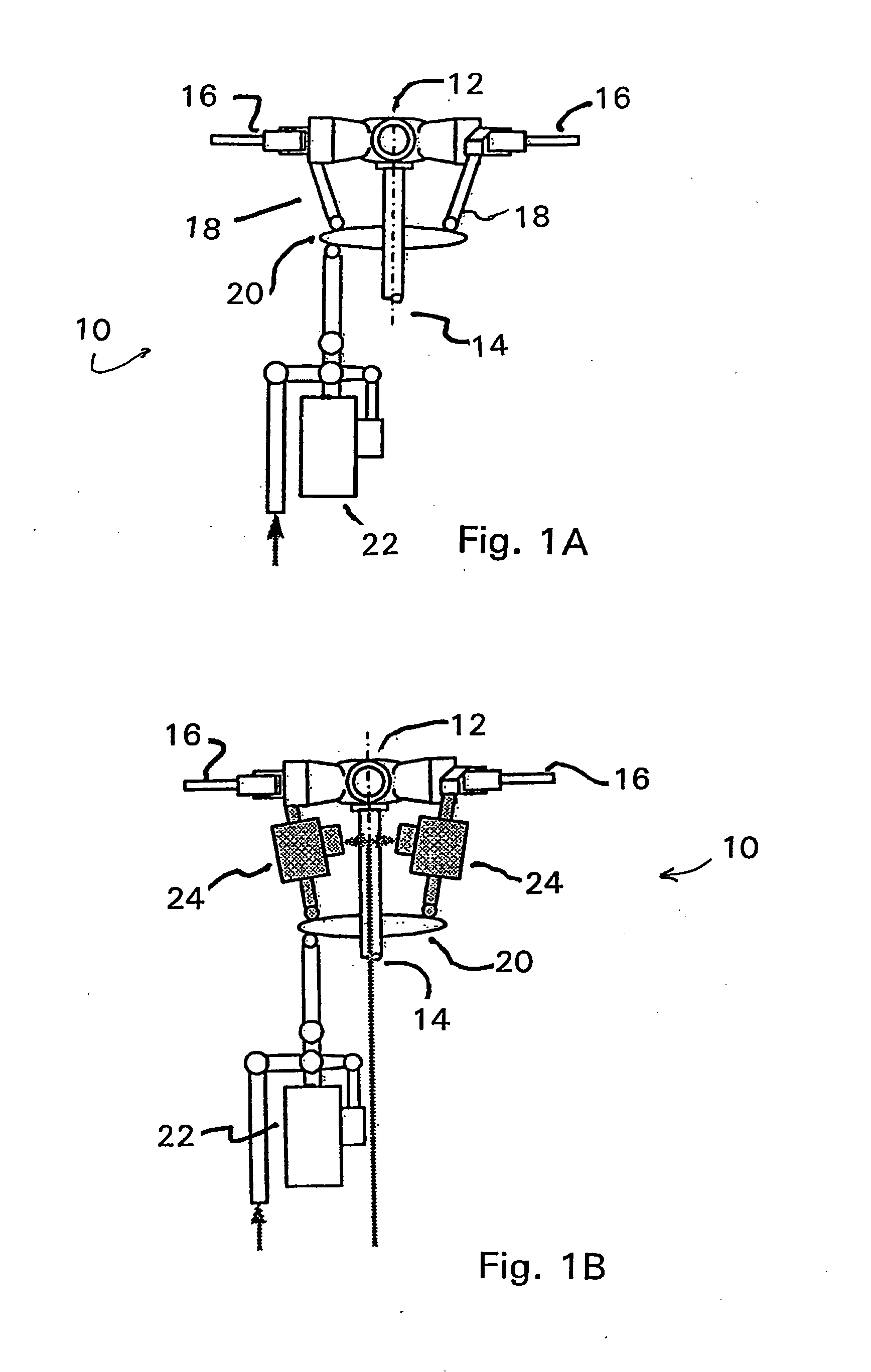
  • Helicopter Rotor Control System with Individual  Blade Control
  • Helicopter Rotor Control System with Individual  Blade Control
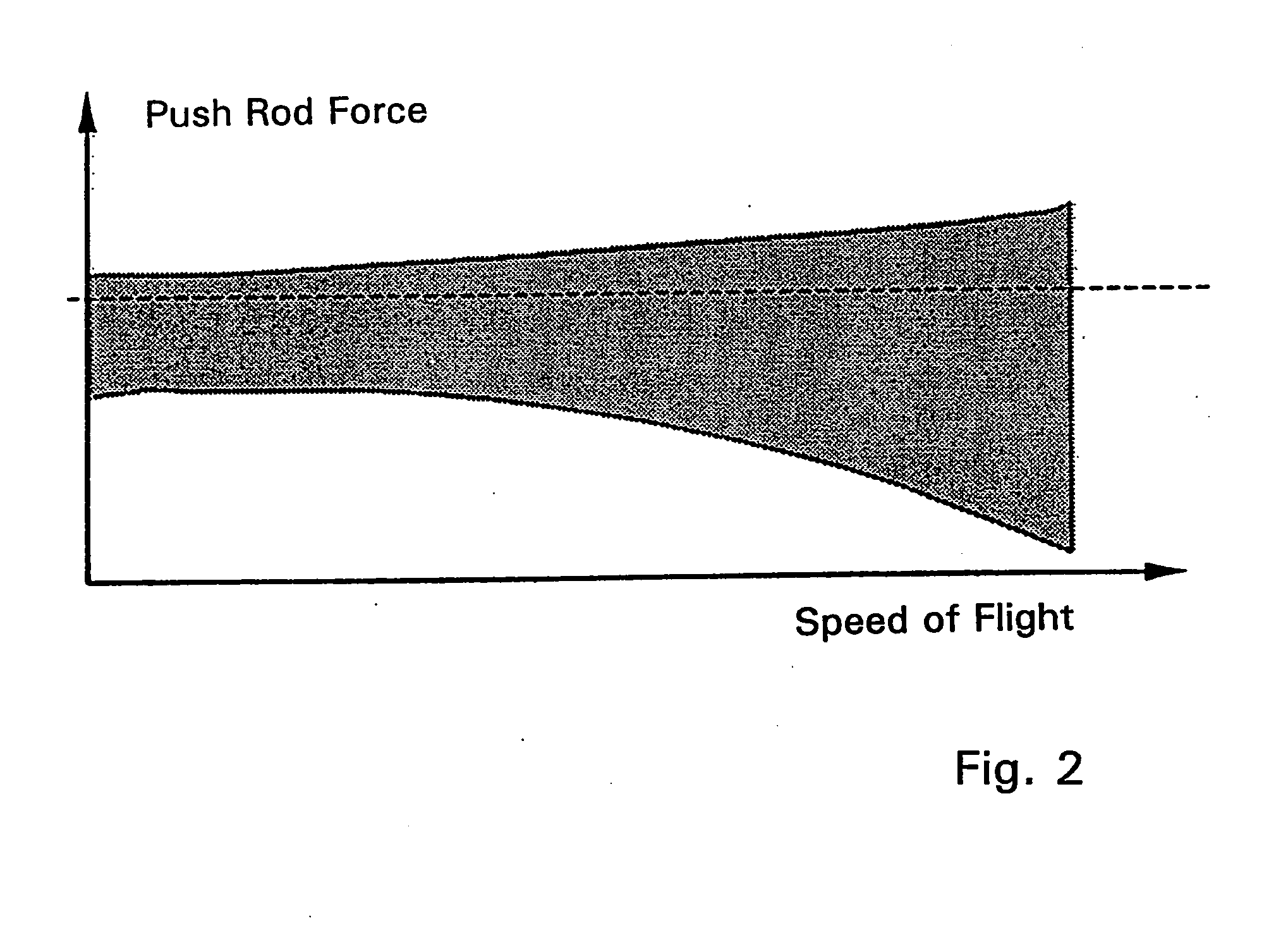
  • Helicopter Rotor Control System with Individual  Blade Control

Examples


Embodiment Construction

A. Introduction

[0026]As described in detail in the following, the present invention provides a helicopter rotor control system having individual pitch control of each of the rotor blades through an individual pitch actuator for each blade and a rotor pitch control system that measures the vibration causing factors acting upon the rotor blades, determines a dynamic rotor pitch control signal for each individual rotor blade, and controls each rotor blade individually through an associated individual pitch actuator to dynamically correct or compensate for the factors causing vibration in each rotor blade individually.

[0027]As discussed above, the rotor control systems of the prior art typically determine a single rotor control signal as a factor of the desired lift from the rotor and the speed and direction signals generated from the pilot controls. That single control signal is then mechanically, electrically or hydraulically phase shifted and applied to the rotor swash plate, or the ...


PUM


Abstract

Controlling the pitch of individual rotor blades of a helicopter to reduce control loads, vibration and noise in or from the rotating rotor control elements. The system generates blade dynamics signals representing dynamic forces acting on either or both of the rotating and non-rotating elements of the helicopter, including rotor blades of a rotating assembly. The system extracts information representing at least one dynamic force, generates a dynamic force compensation output that represents a compensation for the dynamic force, and generates, from flight control signals and the dynamic force compensation output, a compensated pitch actuator control signal for each rotor blade wherein the compensation factor of the pitch control signal compensates for the dynamic force.

Description

FIELD OF THE INVENTION[0001]The present invention relates to a method and apparatus for individual actuation and control of the rotor blades of a helicopter for reduction of noise, vibration, power consumption and control load.BACKGROUND OF THE INVENTION[0002]Common problem in the control and operation of rotary wing aircraft, such as helicopters, is in the control of the pitch of the rotor blades as the rotor rotate to provide lift and control to the helicopter. As is well known, the lift and control provided by the rotor blades is generally achieved by altering the pitch of the rotor blades as the blades rotate, which in turn results in rapidly changing dynamic loads on the blades during rotation, due in part to the dynamic forces induced due to the changing pitches of the blades and in part due to aerodynamic forces acting on the blades. These problems are compounded by dynamic forces, such as vibration, from the helicopter power and drive trains and aerodynamic forces acting on ...

Claims


Application Information

Patent Timeline
IPC IPC(8): B64C27/57
CPCB64C27/001B64C2027/7216Y02T50/34Y02T50/30
Inventor KESSLER, CHRISTOPHFURST, DANIEL
Owner AIRBUS HELICOPTERS TECH GMBH
Why Eureka
Eureka Blog
Learn More