Powder Barrier Coupling for Powder Spray Systems

Inactive Publication Date: 2008-11-13
GM GLOBAL TECH OPERATIONS LLC
View PDF9 Cites 1 Cited by
  • Summary
  • Abstract
  • Description
  • Claims
  • Application Information

AI Technical Summary

Benefits of technology

[0014]The present invention is a powder barrier coupling for a pneumatic line of a powder spray system, wherein the powder barrier coupling is air passable but powder impassable, serving to prevent powder migration in the pneumatic line back to the pneumatic controller.
[0017]Accordingly, it is an object of the present invention to provide a powder barrier coupling for the pneumatic lines of a powder spray system to prevent powder migration in the pneumatic line from entering into the pneumatic controller.

Problems solved by technology

During the operational lifetime of a powder spray system, the pneumatic pinch valves are cycled through many pinching actions, which eventually adversely affects the resiliency and sealing capability of the membrane of the valve.
In that the air control of the pneumatic controller is effected by solenoid valves, the migration of the powder can adversely affect these solenoid valves, and even migrate outside these valves.
In such an untoward operational situation, the powder can then disperse anywhere in the pneumatic controller and the high voltage supply, causing a magnified maintenance problem that is far beyond the scope of the original problem, which was the simple replacement of the faulty membrane.
Additionally, powder can contaminate any of the other pneumatic lines, as for example the purge line, the color changer control line, and the applicator control line, whereby the powder could migrate back to the pneumatic controller and cause deleterious effects thereat.

Method used


Image

  • Powder Barrier Coupling for Powder Spray Systems
  • Powder Barrier Coupling for Powder Spray Systems
  • Powder Barrier Coupling for Powder Spray Systems

Examples


Embodiment Construction

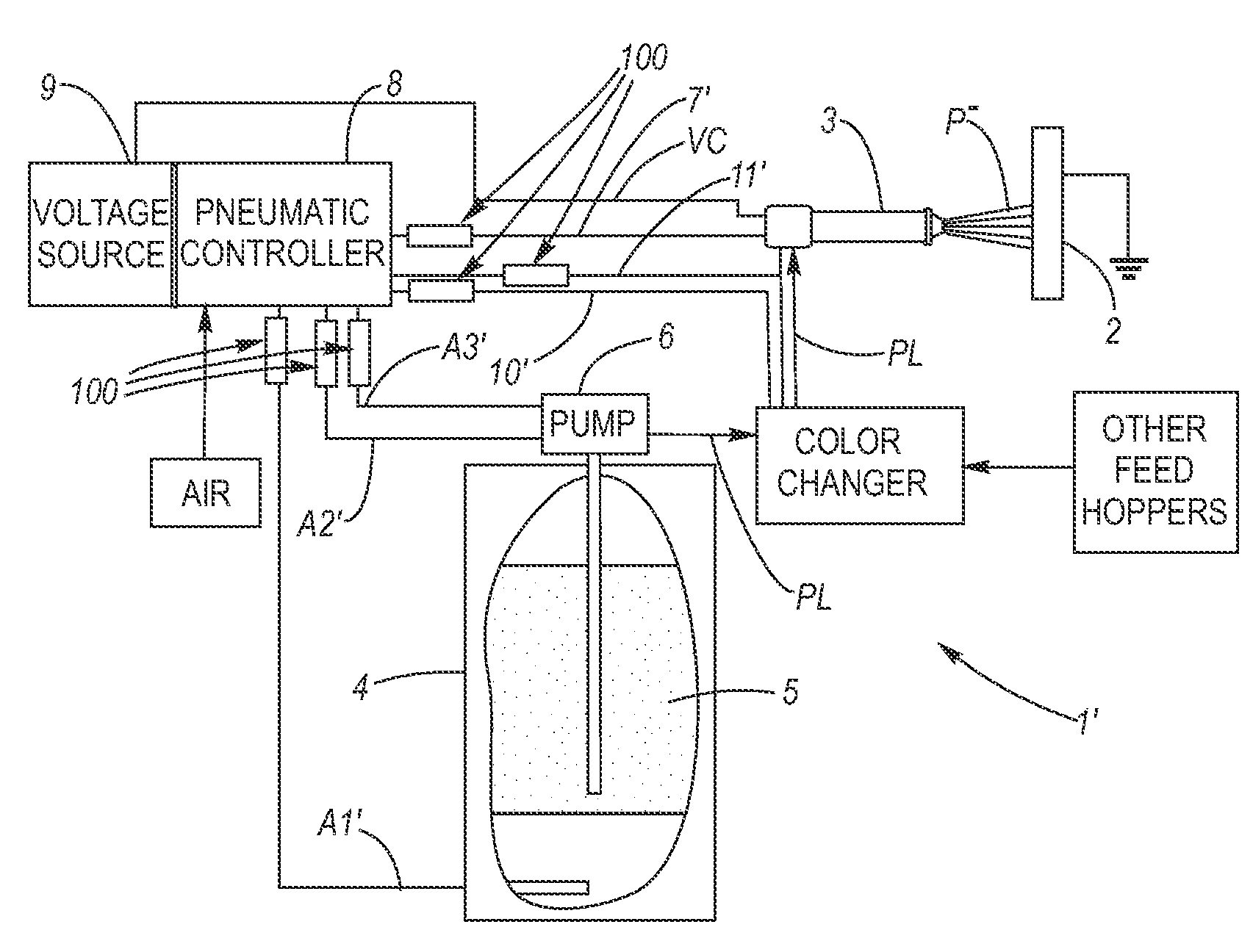
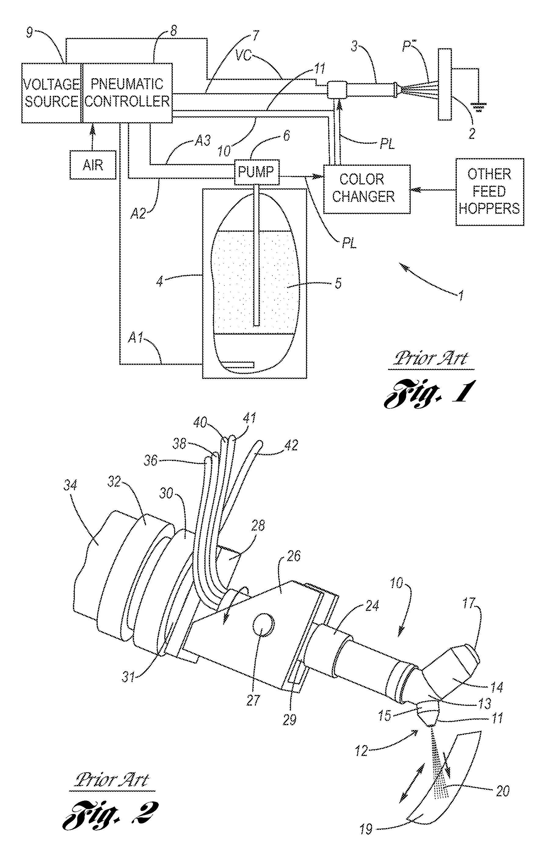
[0029]Referring now to the Drawing, FIGS. 6 through 10B depict an example of a powder barrier coupling 100 for a pneumatic line of a powder spray system, wherein the powder barrier coupling is air passable but powder impassable, serving to prevent powder in the powder spray system from migrating along the pneumatic line back to the pneumatic controller, particularly for a non-limiting example, the pneumatic pinch valve control lines (see lines 40 and 41 in FIGS. 2 and 3) in the event there is a seal failure of the membranes of pneumatic pinch valves (see particularly, in this regard, FIGS. 4 and 5).

[0030]As shown at FIGS. 6 through 8, the powder barrier coupling 100 has an exterior shell 102, preferably of a cylindrically shaped plastic, forming an interior passage 104 between a first end 106 and an opposite second end 108.

[0031]Disposed within the passage is a porous filter media 110 having an average pore size which is predetermined to permit passage therethrough of air, but inhib...


PUM


Abstract

A powder barrier coupling for a pneumatic line of a powder spray system which is air passable but powder impassable. An exterior shell forms a passage. Disposed sealingly within the passage is a porous filter media having an average pore size and thickness which are predetermined to permit passage therethrough of air, but prevent the passage therethrough of powder of a selected average cross-sectional size.

Description

TECHNICAL FIELD[0001]The present invention relates to powder spray systems, and more particularly to a barrier of the pneumatic control lines thereof which permits passage therethrough of air, but prevents the passage therethrough of powder.BACKGROUND OF THE INVENTION[0002]Electrostatic spray applicators are widely used in the coating industry for powder spray coating of substrates such as automotive vehicles. Spray gun applicators mounted on programmable robots used in automated production lines are advantageous in applying uniform coatings of powder to irregularly-shaped substrates.[0003]FIG. 1 schematically depicts a conventional powder spray system 1. A substrate 2 to be powder coated passes an applicator assembly 3. A feed hopper 4 holds a powder 5 in a fluidized state via entry of compressed air through pneumatic line A1 (fluidizing air) into the bottom of the feed hopper. A powder pump 6, for example operating on a venturi principle using a secondary compressed air pneumatic ...

Claims


Application Information

Patent Timeline
IPC IPC(8): B05B1/12
CPCB05B1/16B05B5/032B05B5/1683B05B7/1263
Inventor RAUCH, FRANK P.NORRMALM, ERIC G.KELLY, CHARLOTTE E.VAN DER STEUR, GUNNAR
Owner GM GLOBAL TECH OPERATIONS LLC
Why Eureka
Try Eureka