
Method and Apparatus for the Treatment of Objects, in Particular for the Cleaning of Semiconductor Elements

Active Publication Date: 2008-11-13
RENA
View PDF9 Cites 1 Cited by
  • Summary
  • Abstract
  • Description
  • Claims
  • Application Information

AI Technical Summary

Benefits of technology

[0018]Besides the elimination of the drawbacks of the prior art as mentioned above, an essential advantage of the invention according to a preferred embodiment is that the cleaning of objects can be carried out continuously without the need of a manual or automatic rearrangement or resorting.
[0020]Mechanically, it is possible to arrange a sound source field within a liquid-filled tank in a defined distance with respect to the object to be cleaned.
[0031]According to an embodiment of the present invention, the objects are placed onto a transportation device, e.g. a roller transportation system. Here, the objects are transported by aid of several transport rollers that are arranged one after another and oriented horizontally. The individual transport rollers are arranged within a fluid in such a manner that the respective upper edge of the rollers is positioned approximately at the level of the fluid surface, i.e. the upper border of the fluid, so that the lower side of the respective object is wetted by direct contact with the fluid surface. Here, a meniscus can form at the edges of the object. An interaction of gravity and surface tension then pulls the object down and results in the object remaining in contact with the rollers without floating. By this, the roller conveyor system enables to transport the objects in a controlled and defined manner.
[0035]Besides the advantages already mentioned, the carrying out of the method according to the invention results in a significant reduction of the processing time compared to known methods. It could be demonstrated according to the invention that the common processing time of approximately one hour can be reduced to approx. 10 minutes.

Problems solved by technology

The typical total time of such a cleaning process including drying approximately amounts to one hour and mostly requires several manual or mechanically assisted relocation steps, resulting in relatively high breaking rates.

Method used


Image

  • Method and Apparatus for the Treatment of Objects, in Particular for the Cleaning of Semiconductor Elements
  • Method and Apparatus for the Treatment of Objects, in Particular for the Cleaning of Semiconductor Elements
  • Method and Apparatus for the Treatment of Objects, in Particular for the Cleaning of Semiconductor Elements

Examples


Embodiment Construction

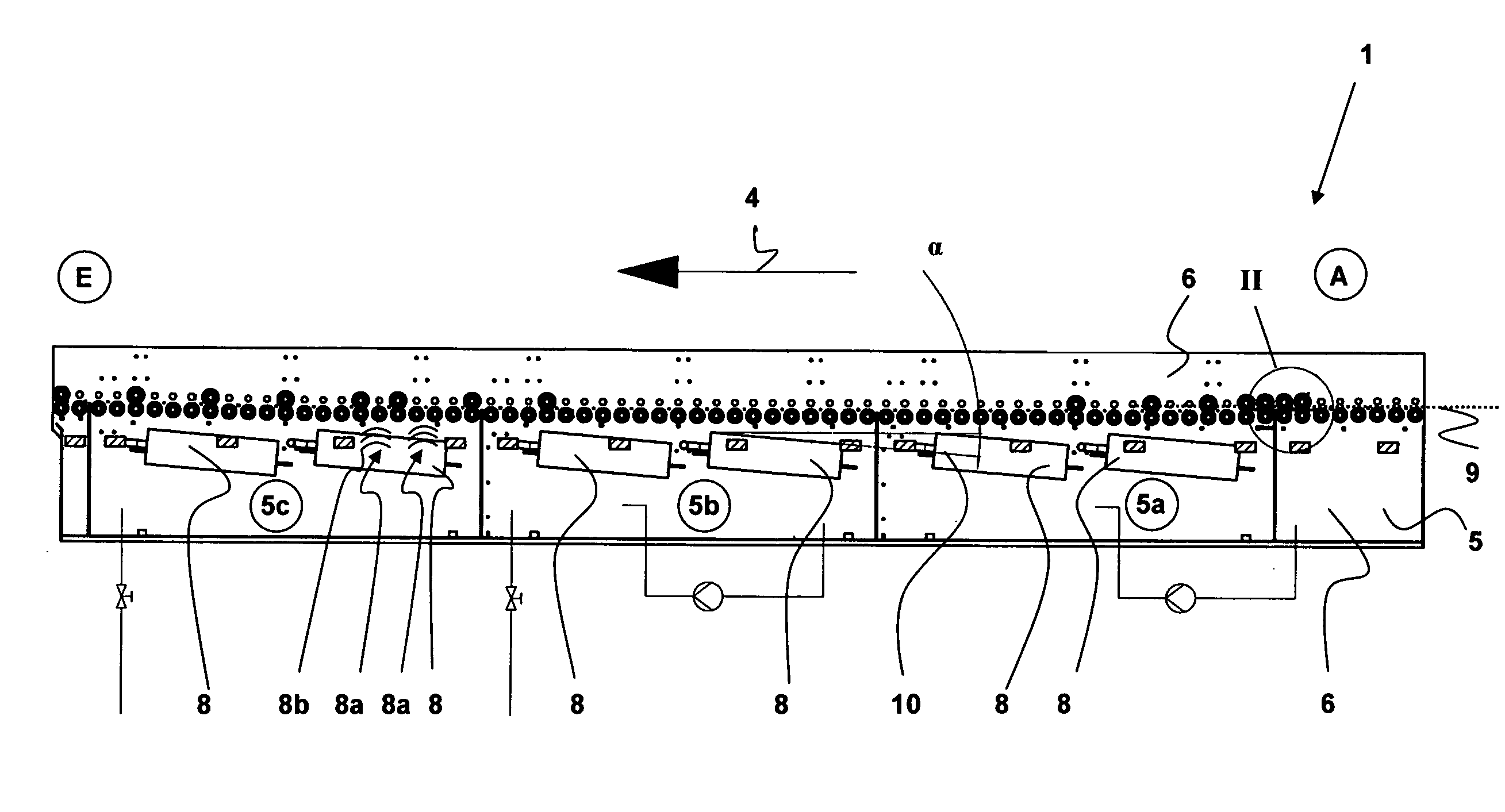
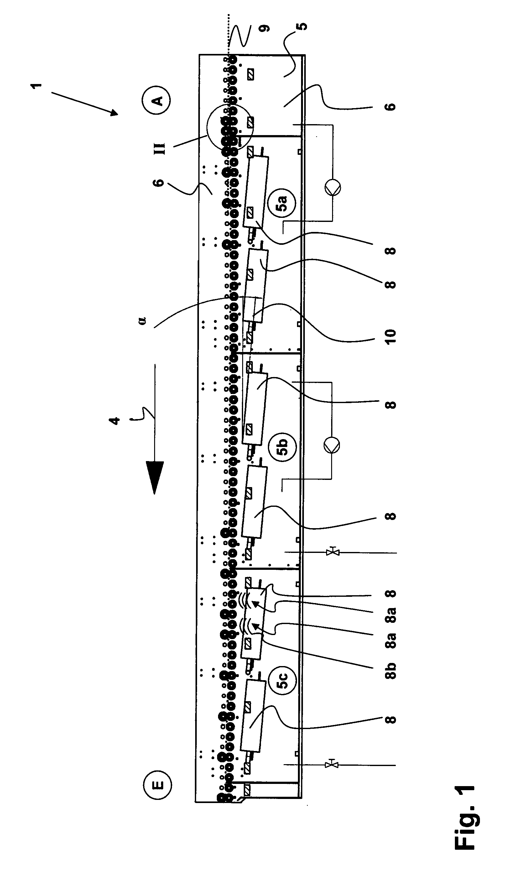
[0042]FIG. 1 schematically shows an apparatus 1 according to the invention for the cleaning of objects 2, in particular of wafers in the form of discs.

[0043]The objects 2 are moved by the transportation device 3 in transport direction 4 through a tank 5. The tank 5 is filled with a liquid 6. The transportation device 3 itself preferably consists of driving rollers 3a and holding-down means 3b (FIG. 2), wherein the driving rollers 3a, due to their rotary motion in direction of arrow 7, serve to drive the objects 2 in transport direction 4. The holding-down means 3b that rotate in counter-movement serve to ensure that the objects 2 do not float in liquid 6.

[0044]The tank 5 is divided into different regions, in so-called segments 5a, 5b, 5c. All segments 5a, 5b, 5c can fluidically be interconnected and are served via the transportation device 3. For the exemplifying embodiment depicted here, at least one sound source field 8 is arranged within each segment 5a, 5b, 5c. This sound source...


PUM

PropertyMeasurementUnit
Temperatureaaaaaaaaaa

Abstract

The invention relates to the continuous cleaning of objects, in particular of semiconductor elements, using ultrasound, wherein the objects to be cleaned are arranged within a liquid. Furthermore, the present invention relates to an apparatus for carrying out the method according to the invention.A basic idea of the invention is that the surface of an object to be cleaned (2) in a tank (5) filled with liquid passes through at least one oscillation maximum that is emitted by at least one sound source (8a) being present in the tank (5). According to one embodiment, the sound source fields (8) that are positioned within the tank (5) are arranged inclined with respect to the transport direction (4).

Description

FIELD OF INVENTION[0001]The invention relates to the cleaning of objects, in particular of semiconductor elements, using ultrasound, wherein the objects to be cleaned are arranged within a liquid. Furthermore, the present invention relates to an apparatus for carrying out the method according to the invention.BACKGROUND OF THE INVENTION[0002]In general, the cleaning with ultrasonic waves is well known. Ultrasonic cleaning is mainly being used in industrial piece-part production and employed especially in electrical engineering, in precision mechanics, in metal working, or also in the production of circuit boards. Other typical fields of application for this type of object cleaning can be found in photo industry as well as in medical technology. The use of ultrasonic waves serves to particularly remove dirt particles from objects, and is suggested when the impurities can only inadequately be reached and removed with mechanical cleaning devices such as, for example, brushes or polishi...

Claims


Application Information

Patent Timeline
IPC IPC(8): H01L21/306B08B3/12H01L21/00
CPCB08B3/123H01L21/02052H01L21/67057
Inventor BURGER, NORBETLOHMANN, MIRKOHERTER, RICHARD
Owner RENA
Learn More