Microstructured optical fibers and methods

a microstructured optical fiber and microstructure technology, applied in the field of optical fibers, can solve the problems of affecting the attenuation of the fiber, reshaping or deformation, and low productivity, and achieve the effects of improving the bend performance of the optical fiber, improving the attenuation, and improving the refractive index

Inactive Publication Date: 2008-11-13
CORNING INC
View PDF14 Cites 16 Cited by
  • Summary
  • Abstract
  • Description
  • Claims
  • Application Information

AI Technical Summary

Benefits of technology

[0010]The consolidated preform having holes therein is then used to make an optical fiber. At least some of the holes formed in the optical fiber preform during the consolidation step remain in the drawn optical fiber. By designing the hole containing region to correspond to the cladding of the optical fiber, these resultant optical fiber can be made to exhibit a core region with a first refractive index and a cladding region having a second refractive index lower than that of the core, the lower refractive index at least partly due to the presence of the holes in the cladding. Alternatively or additional the methods disclosed herein can be used to provide a hole containing region within the cladding to thereby improve the bend performance of the optical fibers. For example, u

Problems solved by technology

There are several disadvantages to the stack and draw method.
The awkwardness of assembling hundreds of very thin canes (defined by rods or tubes), as well as the possible presence of interstitial cavities when stacking and drawing cylindrical canes, may affect dramatically

Method used


Image

  • Microstructured optical fibers and methods
  • Microstructured optical fibers and methods
  • Microstructured optical fibers and methods

Examples


Embodiment Construction

[0026]The methods of the present invention utilizes preform consolidation conditions which are effective to result in a significant amount of gases being trapped in the consolidated glass blank, thereby causing the formation of voids in the consolidated glass optical fiber preform. Rather than taking steps to remove these voids, the resultant preform is used to form an optical fiber with voids therein.

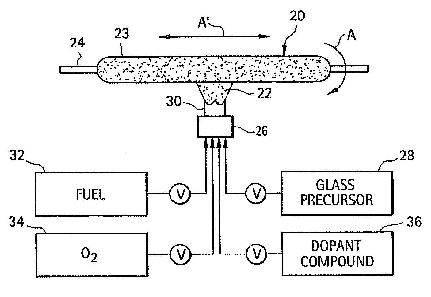
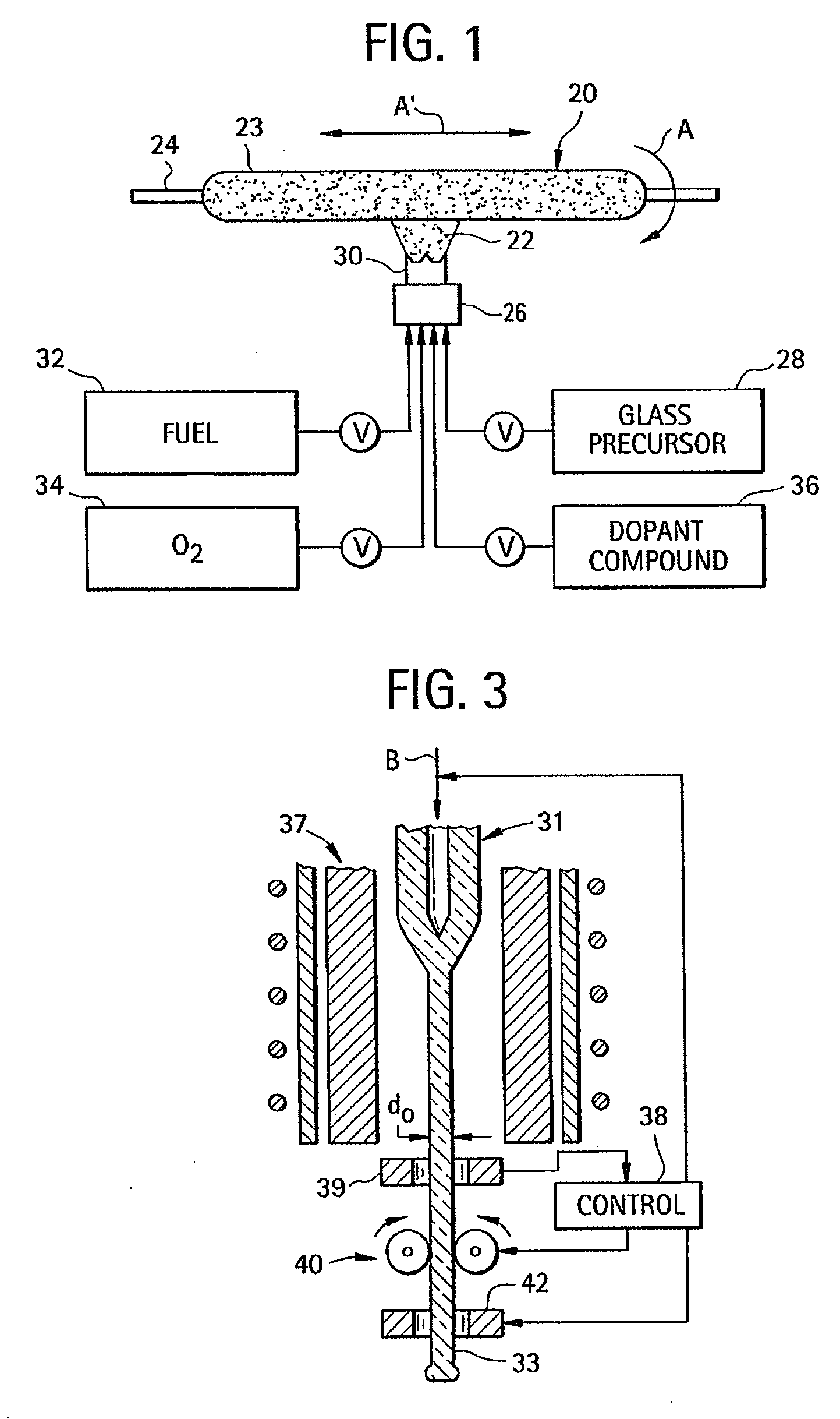
[0027]During the manufacture of transmission optical fibers by conventional soot deposition processes such as the outside vapor deposition (OVD) process or the vapor axial deposition (VAD) process, silica and doped silica particles are pyrogenically generated in a flame and deposited as soot. In the case of OVD, silica soot preforms are formed layer-by-layer by deposition of the particles on the outside of a cylindrical target rod by traversing the soot-laden flame along the axis of the cylindrical target. Such porous soot preforms are subsequently treated with a drying agent (e.g., ch...


PUM

PropertyMeasurementUnit
Temperatureaaaaaaaaaa
Lengthaaaaaaaaaa
Fractionaaaaaaaaaa

Abstract

Method of making a microstructured optical fiber. Silica glass based soot is deposited on a substrate to form at least a portion of an optical fiber preform by traversing a soot deposition burner with respect to said substrate at a burner traverse rate greater than 3 cm/sec, thereby depositing a layer of soot having a thickness less than 20 microns for each of a plurality of burner passes. At least a portion of the soot preform is then consolidated inside a furnace to remove greater than 50 percent of the air trapped in said soot preform, said consolidating taking place in a gaseous atmosphere containing krypton, nitrogen, or mixtures thereof under conditions which are effective to trap a portion of said gaseous atmosphere in said preform during said consolidation step, thereby forming a consolidated preform which when viewed in cross section will exhibit at least 50 voids therein.

Description

CROSS-REFERENCE TO RELATED APPLICATIONS[0001]This application claims the benefit of, and priority of U.S. Provisional Patent Application No. 60 / 928,165 filed on May 8, 2007, the content of which is relied upon and incorporated herein by reference in its entirety.BACKGROUND OF THE INVENTION[0002]1. Field of the Invention[0003]The present invention relates generally to optical fibers, and more specifically to microstructured optical fibers and methods for making microstructured optical fibers.[0004]2. Technical Background[0005]Optical fibers formed of glass materials have been in commercial use for more than two decades. Although such optical fibers have represented a quantum leap forward in the field of telecommunications, work on alternative optical fiber designs continues. One promising type of alternative optical fiber is the microstructured optical fiber, which includes holes or voids running longitudinally along the fiber axis. The holes generally contain air or an inert gas, bu...

Claims


Application Information

Patent Timeline
IPC IPC(8): C03B37/018C03B37/075
CPCC03B37/0142C03B37/01446C03B37/0146C03B37/01466C03B37/02781C03B2203/14C03B2203/42C03B2205/44C03B2205/72
Inventor BOOKBINDER, DANA CRAIGDESORCIE, ROBERT BRETTMCDERMOTT, MARK ALANTANDON, PUSHKAR
Owner CORNING INC
Why Eureka
Try Eureka