
System and Method for Controlling the Axle Load Split Ratio on a Vehicle With Two Front Axles

a technology of axle load and split ratio, which is applied in the direction of transportation and packaging, cycle equipment, instruments, etc., can solve the problems of increasing the turning radius, increasing adding temporary limitations to the transferable load between, so as to minimise improve the handling of the vehicle, and reduce the risk of one or more axle overload

Inactive Publication Date: 2008-10-30
VOLVO LASTVAGNAR AB
View PDF22 Cites 48 Cited by
  • Summary
  • Abstract
  • Description
  • Claims
  • Application Information

AI Technical Summary

Benefits of technology

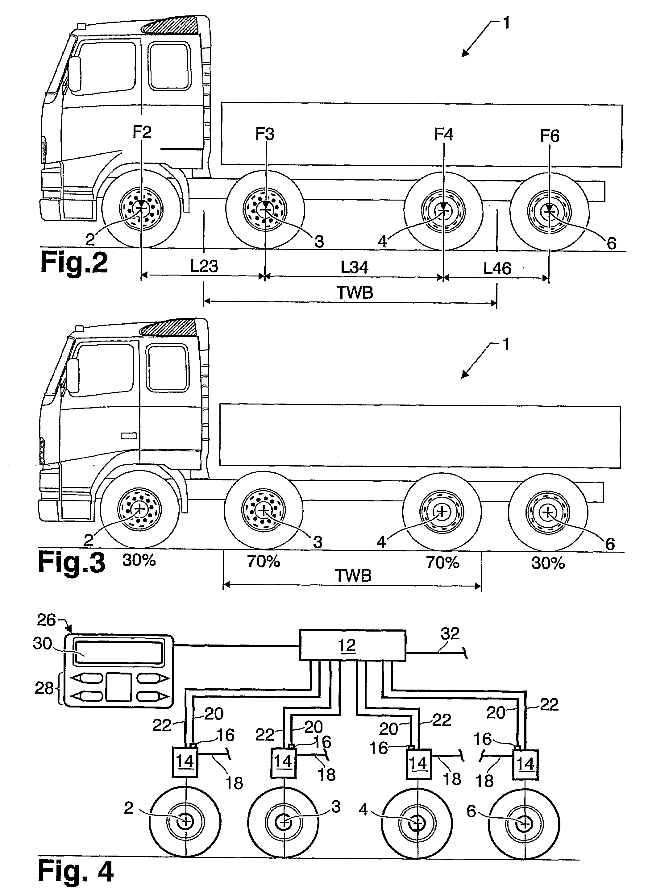
[0004]By controlling the load split between the axles of a vehicle, the theoretical wheelbase can be altered. By doing this, it is possible to optimise the theoretical wheelbase for any given load situation. It may e.g. be necessary to have a small theoretical wheelbase and thereby a small turning radius under some driving conditions. However, minimisation of the theoretical wheelbase may result in load split ratios between the axles that lead to an overload condition for one or more axles. This may only be acceptable or desirable for short periods of time. On the other hand, optimisation of the load split ratio with respect to the loading of the axles may result in a larger turning radius that which is only acceptable under driving conditions where sharp turns can be avoided, such as when driving on motorways.
[0007]By making it possible to find the best compromise between the turning radius and axle loads for a given situation, the handling of the vehicle may be improved with a minimised risk for overloading one or more of the axles.
[0008]A variable theoretical wheelbase for vehicles with two front axles may also improve the efficiency of the transportation with respect to several aspects such as time, wear and fuel consumption. Furthermore, it may also make it easier to achieve legal axle loads for uneven load distributions. It is desirable to improve the transport and handling efficiency of a vehicle with respect to time, wear and fuel consumption.
[0009]It is desirable to improve the loading and unloading situation due to a larger degree of flexibility with respect to load distribution. The possibility of adjusting the load split ratio after the loading decreases or removes the need to avoid uneven load distribution. It is also possible to adjust the load split ratio during a loading or unloading situation.
[0010]It is desirable to improve the tipping stability of tipper vehicles and swap body vehicles.
[0033]The present invention provides a large flexibility as to adjustment of the theoretical wheelbase when loading and unloading the vehicle due to the possibility of adjusting the load split afterwards. This advantage is even larger for vehicles that are partly loaded and / or unloaded at several points along a given route, since the present invention removes or minimises the need to repack the load.

Problems solved by technology

However, minimisation of the theoretical wheelbase may result in load split ratios between the axles that lead to an overload condition for one or more axles.
On the other hand, optimisation of the load split ratio with respect to the loading of the axles may result in a larger turning radius that which is only acceptable under driving conditions where sharp turns can be avoided, such as when driving on motorways.
These road limits may be temporary limits connected to season variations such as when the ground is thawing, or it may be limits for certain bridges.
The controller means may further be adapted to receive and process input from an electronic brake system of the vehicle, said input adding temporary limitations to the transferable loads between the axles due to the present dynamic load conditions on each axle.
The method may further comprise the steps of receiving and processing input from an electronic brake system of the vehicle, the input adding limitations, preferably temporary limitations, to the transferable loads between the axles due to the present dynamic load conditions on each axle.

Method used


Image

  • System and Method for Controlling the Axle Load Split Ratio on a Vehicle With Two Front Axles
  • System and Method for Controlling the Axle Load Split Ratio on a Vehicle With Two Front Axles
  • System and Method for Controlling the Axle Load Split Ratio on a Vehicle With Two Front Axles

Examples


Embodiment Construction

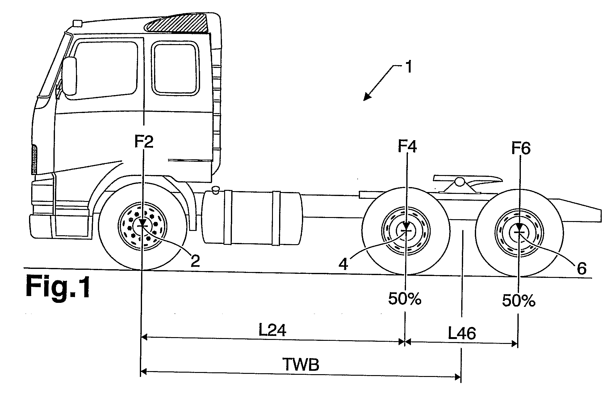
[0040]FIG. 1 illustrates a known vehicle with a theoretical wheelbase denoted TWB. The vehicle 1 is equipped with a front axle 2 and a bogie with two rear axles 4, 6. The theoretical wheelbase TWB is calculated depending on the load split between the axles. The general equation for the theoretical wheelbase, TWB, for such a vehicle is:

TWB=I24+(F6*I46) / (F4+F6)

[0041]where I24 and I46 are the distances between the first and second axles 2, 4 and the second and third axles 4, 6, respectively. F4 and F6 are the loads on the second and third axles 4, 6, respectively.

[0042]In FIG. 1 the load split between the rear axles 4, 6 is 50 / 50 which means that the theoretical wheelbase is the distance from the front axle 2 to midway between the rear axles 4, 6. This later point may be referred to as the theoretical rear axle centreline. By changing the load split ratio between the rear axles, the theoretical wheelbase can be altered. On a vehicle where the rearmost axle is a liftable, the theoretica...


PUM


Abstract

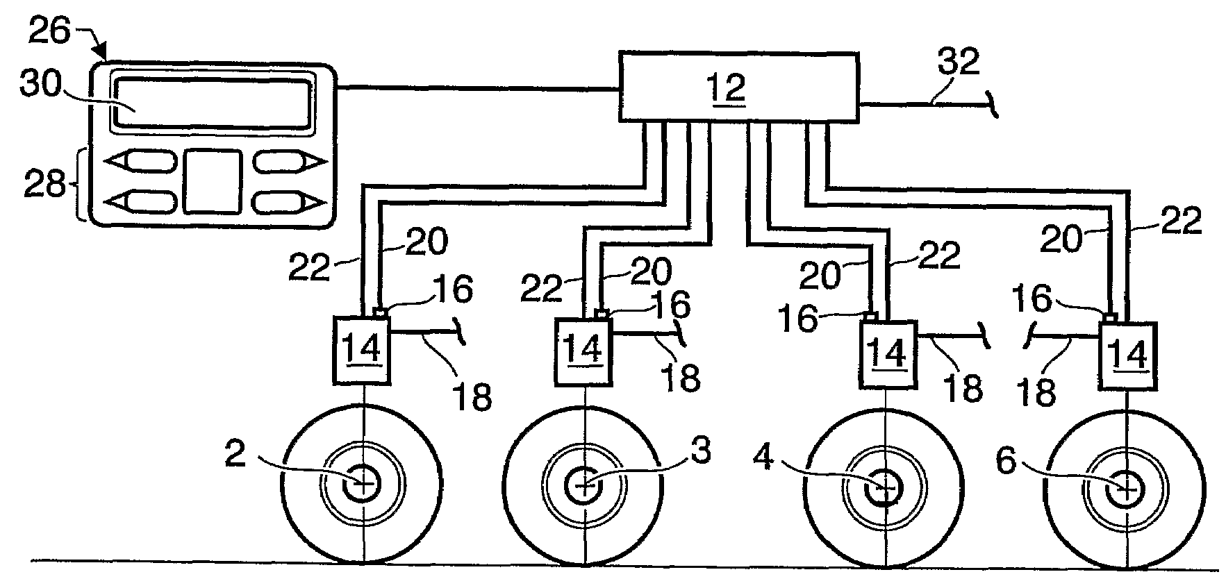
A system is provided for controlling the load split between the axles and thereby the theoretical wheelbase of a vehicle having two front axles being suspended in suspension units at least some of which have springs with adjustable stiffness. A method for controlling the load split between the axles and to a motor vehicle including such a system and / or by use of such a method is also disclosed.

Description

BACKGROUND AND SUMMARY[0001]The present invention relates to motor vehicles having two front axles and, more specifically, to controlling the distribution of axle loads and theoretical wheelbase of such vehicles. The invention relates to all types of motor vehicles including rigid trucks and tractors with and without trailers.[0002]For vehicles with three or more axles, the theoretical wheelbase depends on the load split between the axles. For a truck with a single front axle and a rear bogie, the theoretical wheelbase will be the distance between the front axle and a position between the rear axles. If the load split between the rear axles is 50%, this position will be in the middle of the axles. Depending on the distribution of the goods loaded on the vehicle, the theoretical wheelbase will vary. The theoretical wheelbase will influences e.g. the turning radius of the vehicle, and it is therefore often necessary to find a compromise between the desired turning characteristics of t...

Claims


Application Information

Patent Timeline
IPC IPC(8): B60G17/018
CPCB60G17/019B60G17/0523B60G2300/0262B60G2400/61B60G2400/63G01G19/08B60G2600/04B60G2600/20B60G2800/702B60G2800/915B60G2400/954B60G17/0155B60G17/052
Inventor REGNELL, HANSLILJEBLAD, BENNYGUSTAFSSON, JENS
Owner VOLVO LASTVAGNAR AB
Learn More