
Catalytic Olefin Block Copolymers with Controlled Block Sequence Distribution

a technology of catalytic olefin and copolymer, which is applied in the field of catalytic olefin block copolymer with controlled block sequence distribution, can solve the problems of poor process economics, limited catalyst productivity, and inability to adapt readily, and achieves the effect of high tacticity or crystallinity

Active Publication Date: 2008-10-30
DOW GLOBAL TECH LLC
View PDF5 Cites 226 Cited by
  • Summary
  • Abstract
  • Description
  • Claims
  • Application Information

AI Technical Summary

Benefits of technology

[0029]In yet another embodiment of the invention, the shuttling agent employed in the foregoing processes possesses multiple sites for undergoing polymer exchange, that is, it is multi-centered, especially two centered, which uniquely causes the formation of a polymer product comprising copolymers according to the invention containing three or more distinct polymer segments after undergoing sequential polymerization in two reactors or zones connected in series.
[0030]Highly desirably, the pseudoblock copolymers formed according to the present invention are characterized by terminal blocks or segments of polymer having higher tacticity or crystallinity from the central block or segment. Even more preferably, the central polymer block or segment is relatively amorphous or even elastomeric.
[0031]In a still further embodiment of the present invention, there is provided a polymer mixture comprising: (1) an organic or inorganic polymer, preferably a homopolymer of ethylene or of propylene and / or a copolymer of ethylene or propylene with one or more copolymerizable comonomers, and (2) a pseudo-block copolymer according to the present invention or prepared according to the process of the present invention. In a desirable embodiment component (1) is a matrix polymer comprising high density polyethylene or isotactic polypropylene and component (2) is an elastomeric pseudo-block copolymer containing two or three distinct regions of differentiated comonomer incorporation. In a preferred embodiment, component (2) comprises occlusions of the matrix polymer formed during compounding of components (1) and (2).
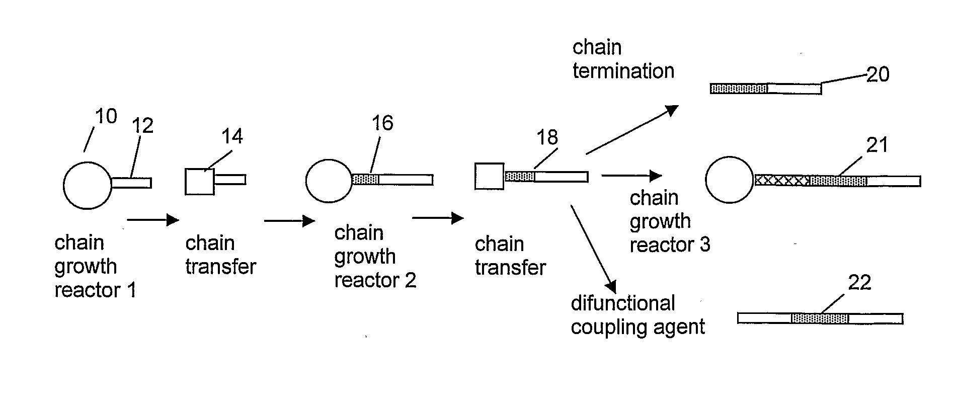
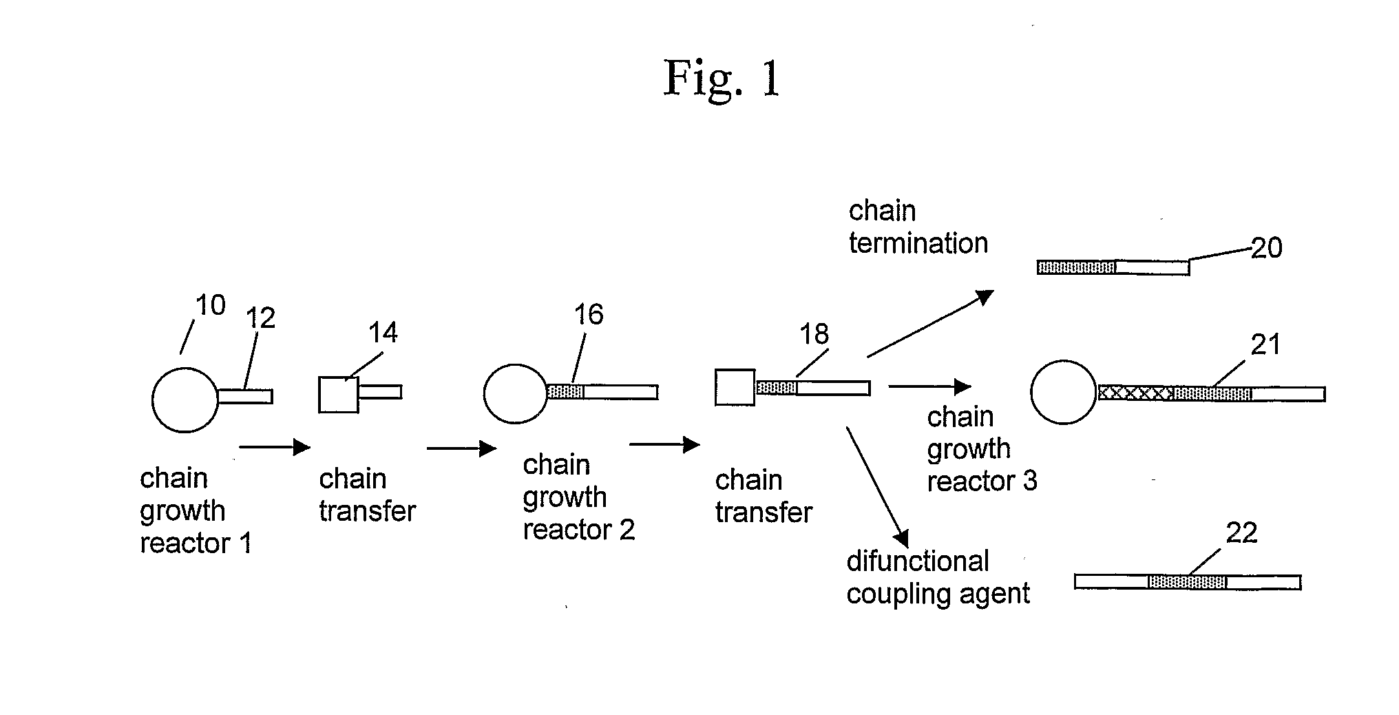
[0032]While the foregoing process has been described as preferably forming a diblock product, it is an additional object of the invention to prepare multi-block copolymers, including hyper-branched or dendrimeric copolymers, through coupling of polymer terminated with a chain shuttling agent exiting the second reactor or zone (or any subsequent reactor or zone) using a difunctional or polyfunctional coupling agent. In addition, if more than two reactors are employed, the product resembles that made by living polymerization in more than one reactor, with the difference that each block of the present polymers possesses a most probable distribution of molecular weights and composition. In particular, the polydispersity of the present polymers is generally less than 2.0 and approaches 1.5 for product made in two reactors. The theoretical limit of Mw / Mn generally equals the value of (1+1 / n), where n is the number of reactors employed in the polymer's production, in accordance with the calculations of J. Appl. Poly. Sci., 92, 539-542 (2004). In general, the average number of blocks in the absence of coupling of the present polymers will be equal to the number of polymerization will normally include quantities of conventional polymer depending on the efficiency of the particular shuttling agent employed under the conditions of the polymerization.

Problems solved by technology

Unfortunately, these methods of preparing block copolymers require sequential monomer addition with polymerization to relative completeness and the types of monomers that can styrene and butadiene to form a SBS type block copolymer, each polymer chain requires a stoichiometric amount of initiator and the resulting polymers have extremely narrow molecular weight distribution, Mw / Mn, preferably from 1.0 to 1.3.
Additionally, anionic and free-radical processes are relatively slow, resulting in poor process economics, and not readily adapted to polymerization of α-olefins.
Disadvantageously, such processes require sequential monomer addition and result in the production of only one polymer chain per active catalyst center, which limits catalyst productivity.
In addition, the requirement of relatively low process temperatures but high conversion increases the process operating costs, making such processes unsuited for commercial implementation.
Moreover, the catalyst cannot be optimized for formation of each respective polymer type, and therefore the entire process results in production of polymer blocks or segments of less than maximal efficiency and / or quality.
For example, formation of a certain quantity of prematurely terminated polymer is generally unavoidable, resulting in the forming of blends having inferior block copolymers having Mw / Mn of 1.5 or greater, the resulting distribution of block lengths is relatively inhomogeneous, not a most probable distribution.
Disadvantageously, the respective stereoisomers of such metallocenes generally fail to possess significant difference in polymer formation properties and are incapable of forming both highly crystalline and amorphous block copolymer segments, for example, from a given monomer mixture under fixed reaction conditions.
Moreover, because the relative ratio of the two “fluxional” forms of the catalyst cannot be varied, there is no ability, using “fluxional” catalysts, to vary polymer block composition or to vary the ratio of the respective blocks.

Method used


Image

  • Catalytic Olefin Block Copolymers with Controlled Block Sequence Distribution
  • Catalytic Olefin Block Copolymers with Controlled Block Sequence Distribution
  • Catalytic Olefin Block Copolymers with Controlled Block Sequence Distribution

Examples


specific embodiments

[0626]The following specific embodiments of the invention and combinations thereof are especially desirable and hereby delineated in order to provide detailed disclosure for the appended claims.

[0627]1. A process for the polymerization of one or more addition polymerizable monomers, preferably of two or more addition polymerizable monomers, especially ethylene and at least one copolymerizable comonomer, propylene and at least one copolymerizable comonomer having from 4 to 20 carbons, or 4-methyl-1-pentene and at least one different copolymerizable comonomer having from 4 to 20 carbons, to form a copolymer comprising two regions or segments of differentiated polymer composition or properties, especially regions comprising differing comonomer incorporation index, said process comprising:

[0628]1) contacting an addition polymerizable monomer or mixture of monomers under addition polymerization conditions, preferably uniform or homogeneous polymerization conditions, in a reactor or react...

example 1

Continuous Solution Polymerization Reactions

[0679]Polymer samples according to the invention and comparative polymer example are prepared in two well mixed, solution reactors, connected in series. The reactors are loop reactors providing reagents (Catalyst A-1, Cocatalyst 1, and shuttling agent SA1), as well as polymer are dissolved in the solvent during the polymerization process in the first reactor and continuously transferred to the second reactor for continued polymerization. Product is continuously removed from the second reactor, the catalyst system deactivated, and the polymer recovered by devolatilization. Recovered solvent / monomer mixture is condensed, purified, and recycled to both reactors. Suitable reactors and operating conditions for use herein are disclosed in U.S. Pat. No. 6,355,741, 5,977,251 or 5,684,097.

[0680]For the comparative examples, no chain shuttling agent (SA) is employed resulting in the formation of blends of polymers having differing levels of crystall...

example 2

Continuous Solution Polymerization Reactions

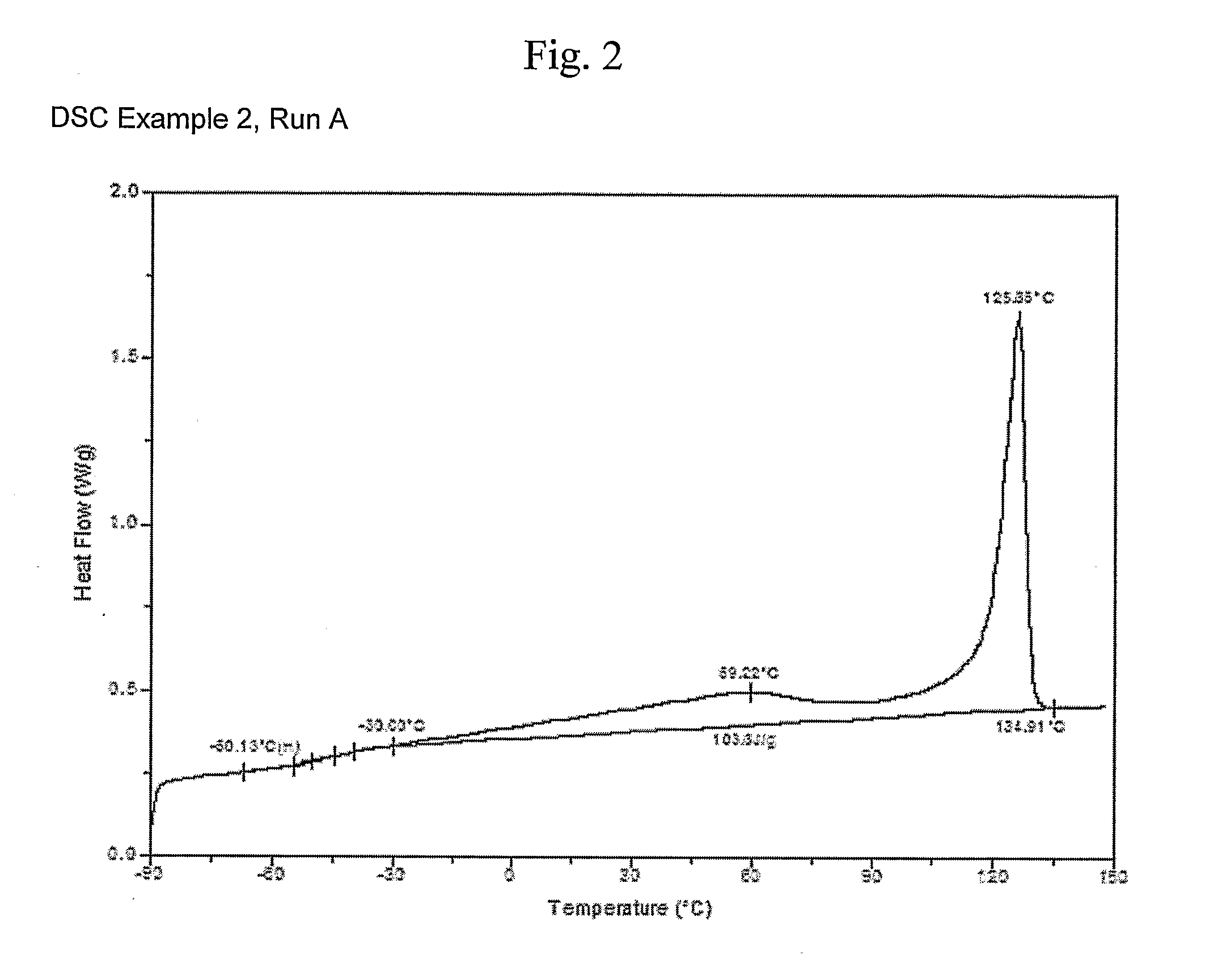
[0682]Ethylene / 1-octene copolymers are prepared using two continuous stirred tank reactors (CSTR) connected in series. Each reactor is hydraulically full and set to operate at steady state conditions. The shuttling agent (SA1) is added to the first reactor along with catalyst A-1, Cocatalyst 1, a scavenger (triisobutylaluminum modified methylalumoxane MMAO, available from Akzo-Noble, Inc.), and solvent (mixed alkanes (Isopar™ E, available from ExxonMobil Chemicals, Inc.). Operating conditions for the two reactors are provided in Tables 5 and 6. Polymer properties are provided in Table 7 and in FIGS. 2-9.

TABLE 5Process Conditions First CSTR Reactor.Cat. A-1Cat. A-1Cocat.CocatMMAOMMAOSA12SA1Solv.C2H4C8H16H2TConc.FlowConc.FlowConcFlowConcFlowR-1Runkg / hrkg / hrkg / hrSccm1° C.ppm Hfkg / hrppmkg / hrppm Alkg / hrppm Znkg / hrConv.4Split5A*12.01.420.031501309320.2617090.311230.2750088.732111.5″0.050125″0.08″0.09″0135000.14191.0″*comparative, not an example ...


PUM

PropertyMeasurementUnit
molecular weight distributionaaaaaaaaaa

Abstract

A process for the polymerization of one or more addition polymerizable monomers and the resulting polymer products, said process comprising: 1) contacting an addition polymerizable monomer or mixture of monomers under addition polymerization conditions in a reactor or reactor zone with a composition comprising at least one olefin polymerization catalyst and a cocatalyst and characterized by the formation of polymer chains from said monomer or monomers; 2) transferring the reaction mixture to a second reactor or reactor zone and optionally adding one or more additional reactants, catalysts, monomers or other compounds prior to, commensurate with, or after said transfer; and 3) causing polymerization to occur in said second reactor or reactor zone to form polymer chains that are differentiated from the polymer chains formed in step 1); said process being characterized by addition of a chain shuttling agent to the reaction mixture prior to, during, or subsequent to step 1) such that at least some of the resulting polymer molecules from step 3) comprise two or more chemically or physically distinguishable blocks or segments.

Description

CROSS REFERENCE STATEMENT[0001]This application claims the benefit of U.S. Provisional Application No. 60 / 717,545, filed Sep. 15, 2005. For purposes of United States patent practice, the contents of this provisional application are herein incorporated by reference.BACKGROUND OF THE INVENTION[0002]The present invention relates to a process for polymerizing a monomer or mixtures of two or more monomers such as mixtures of ethylene and one or more comonomers, to form an interpolymer product having unique physical properties, to a process for preparing such interpolymers, and to the resulting polymer products. In another aspect, the invention relates to the articles prepared from these polymers. The inventive polymers comprise two or more differing regions or segments (blocks), each block being characterized by a generally uniform chemical composition, causing the polymer to possess unique physical properties. These pseudo-block copolymers and polymeric blends comprising the same are us...

Claims


Application Information

Patent Timeline
Patent Type & Authority Applications(United States)
IPC IPC(8): C08F297/00C08F2/01
CPCC08F4/659C08F4/65908C08F4/6592C08F4/65927C08F10/00C08F2410/01C08F210/16C08F297/08C08F210/06C08F4/65912C08F2/38C08F4/64048C08F4/64193C08F4/64148C08F4/64144C08F210/14C08F2500/03C08F2500/20C08F2500/12C08F2500/08C08F2/001C08F4/02C08F2/01
Inventor CARNAHAN, EDMUND M.HUSTAD, PHILLIP D.KUHIMAN, ROGER L.WENZEL, TIMOTHY T.
Owner DOW GLOBAL TECH LLC
Learn More