
Operation method of non-volatile memory and method of improving coupling interference from nitride-based memory

a non-volatile memory and coupling interference technology, applied in the field of operation methods for a memory structure, can solve problems such as threshold voltage shift (vt shift), and achieve the effect of improving the coupling interference of the nitride-based memory

Active Publication Date: 2008-10-30
MACRONIX INT CO LTD
View PDF5 Cites 0 Cited by
  • Summary
  • Abstract
  • Description
  • Claims
  • Application Information

AI Technical Summary

Benefits of technology

[0012]In solution, the present invention is directed to provide an operation method for a non-volatile memory and a method for improving the coupling interference of the nitride-based memory, which can improve the coupling interference of the nitride-based memory and various derived problems.
[0021]According to an embodiment of the present invention, in the method for improving the coupling interference of the nitride-based memory structure, the aforementioned first positive voltage is 0.5˜2 volt.
[0022]According to an embodiment of the present invention, in the method for improving the coupling interference of the nitride-based memory structure, the aforementioned second positive voltage is 0.5˜2 volt.
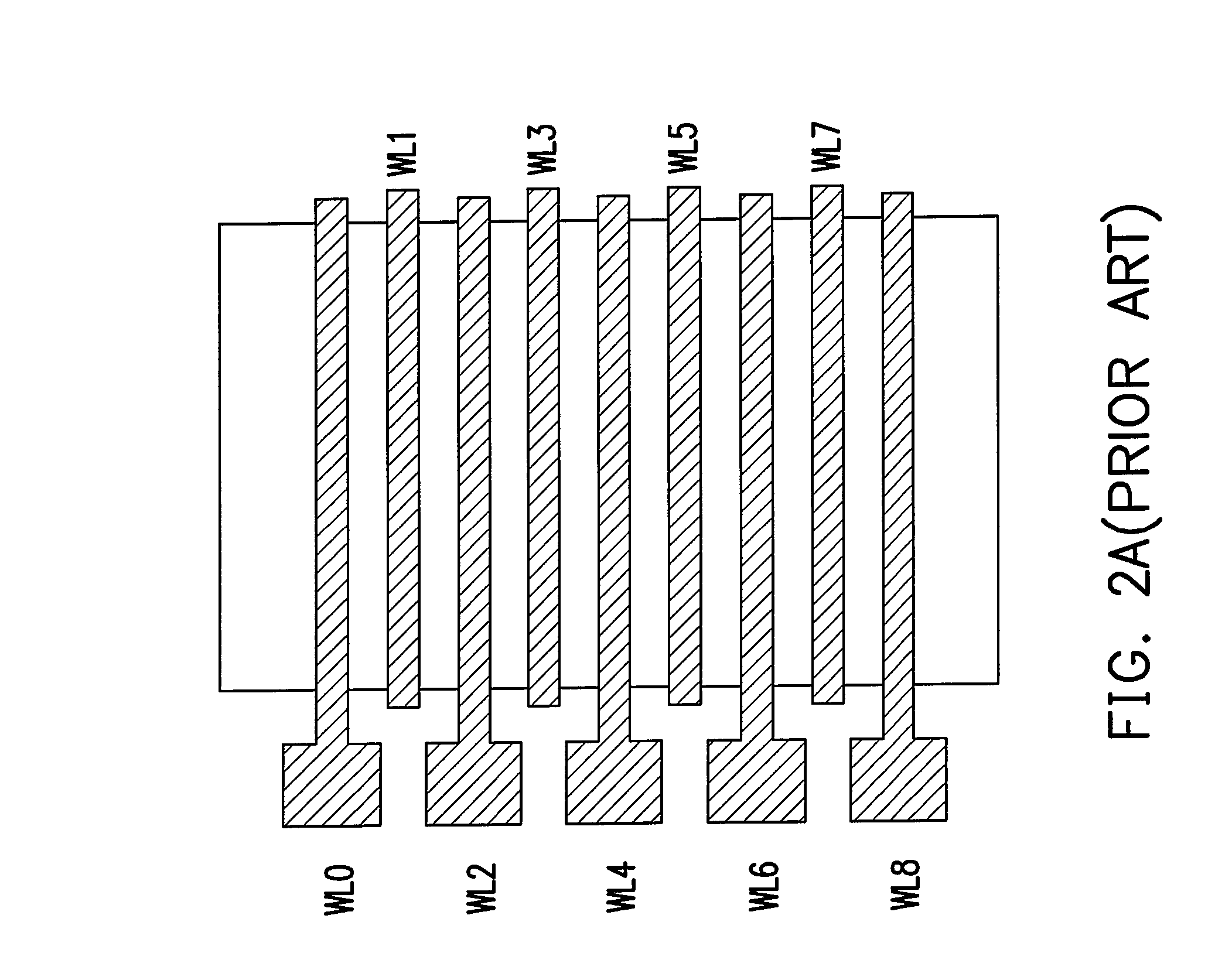
[0026]In the method of the present invention, when performing the reading operation to the selected memory cell, the positive voltages are applied to the word lines adjacent to the memory cells, thereby reducing the coupling interference and preventing the threshold voltage from being increased and affecting the operation of devices. Moreover, the present invention can overcome the limitations of miniaturization and as a result, fabricating techniques of the memory cells are advancing toward ever-miniaturizing dimensions.

Problems solved by technology

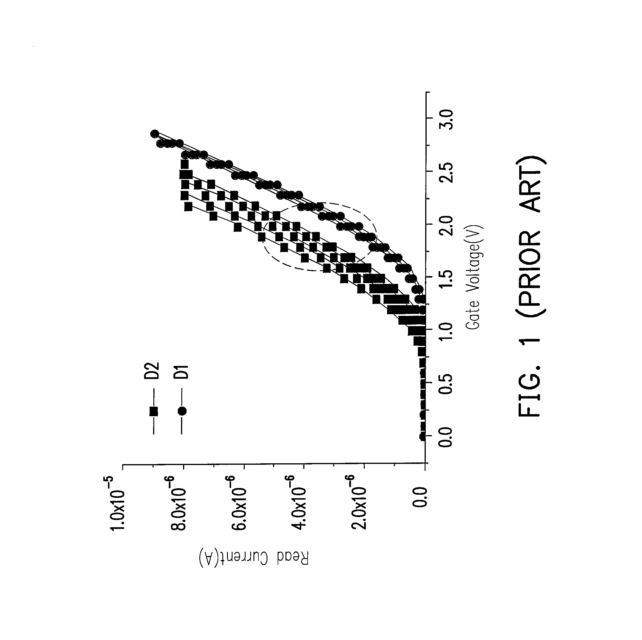
The coupling interference issue occurs when the distance between each two devices is too close, thereby resulting in a threshold voltage shift (Vt shift), which is the most important limitation when the aforementioned floating gate based memory cell is continuingly miniaturized.

Method used


Image

  • Operation method of non-volatile memory and method of improving coupling interference from nitride-based memory
  • Operation method of non-volatile memory and method of improving coupling interference from nitride-based memory
  • Operation method of non-volatile memory and method of improving coupling interference from nitride-based memory

Examples


Embodiment Construction

[0038]Reference will now be made in detail to the present preferred embodiments of the invention, examples of which are illustrated in the accompanying drawings. Wherever possible, the same reference numbers are used in the drawings and the description to refer to the same or like parts.

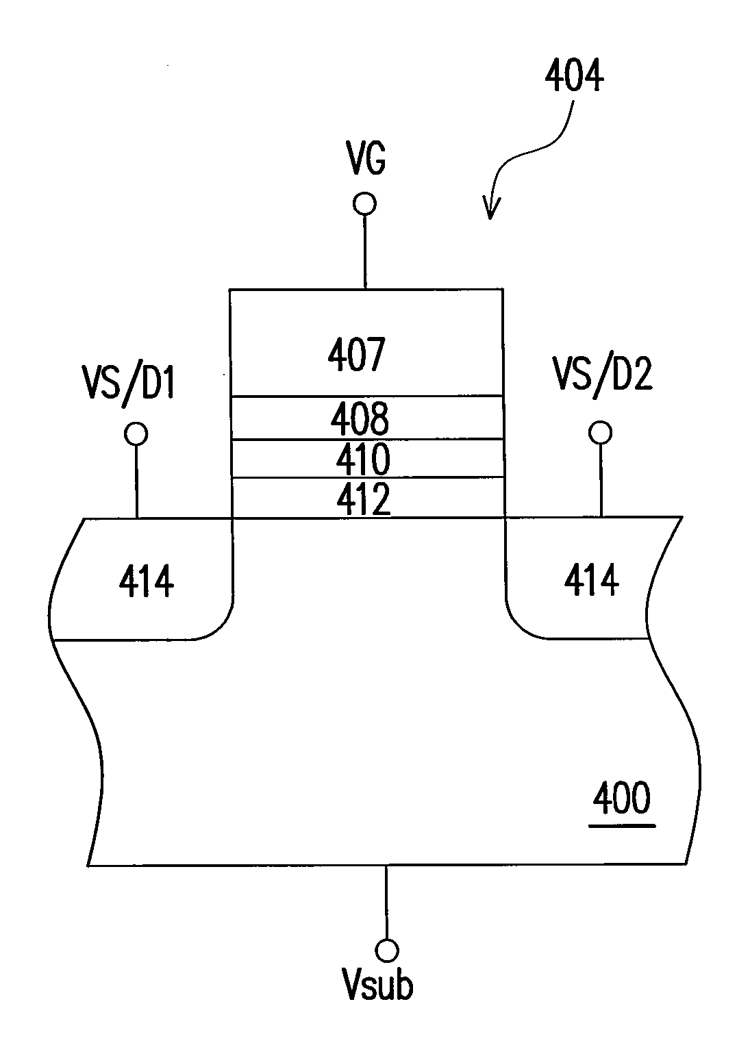
[0039]FIG. 4A is a top view of a non-volatile memory array structure according to one embodiment of the present invention. FIG. 4B is a cross-sectional view of a memory cell along line I-I′ in FIG. 4A. The numbers of the memory cells, word lines and bit lines in FIG. 4A are merely exemplary, not used to limit this present invention.

[0040]Referring to FIG. 4A, the non-volatile memory of this embodiment mainly comprises: a substrate 400, a plurality of buried bit lines 402, a plurality of memory cells 404 and a plurality of word lines (WL) 406. The buried bit lines 402 are disposed in the substrate 400 and arranged in parallel in a column direction (Y direction) and every buried bit line 402 is, for ex...


PUM


Abstract

An operation method of a non-volatile memory is provided. The operation method is that a reading operation is performed to a selected nitride-based memory cell, a first positive voltage is applied to a word line adjacent to one side of the selected memory cell and a second positive voltage is applied to another word line adjacent to the other side of the selected memory cell. The operation method of this present invention not only can reduce a coupling interference issue but also can obtain a wider operation window.

Description

CROSS-REFERENCE TO RELATED APPLICATION[0001]This application claims the benefit of U.S. Provisional Application No. 60 / 913,817, filed on Apr. 25, 2007. The entirety of the above-mentioned patent application is hereby incorporated by reference herein and made a part of this specification.BACKGROUND OF THE INVENTION[0002]1. Field of the Invention[0003]The present invention relates to an operation method for a memory structure, in particular, to an operation method for a non-volatile memory and a method for improving coupling interference of a nitride-based memory.[0004]2. Description of Related Art[0005]A typical non-volatile memory cell has a floating gate and a control gate made by doped polysilicon. The floating gate is disposed between the control gate and a substrate. And, the floating gate is in a floating state and is not electrically connected to any circuit. The floating gate is used to store charges, while the control gate is used to control a data writing / reading operation....

Claims


Application Information

Patent Timeline
IPC IPC(8): G11C11/34
CPCG11C16/0466G11C16/26
Inventor CHANG, YAO-WENWU, GUAN-WEILU, TAO-CHENG
Owner MACRONIX INT CO LTD
Learn More