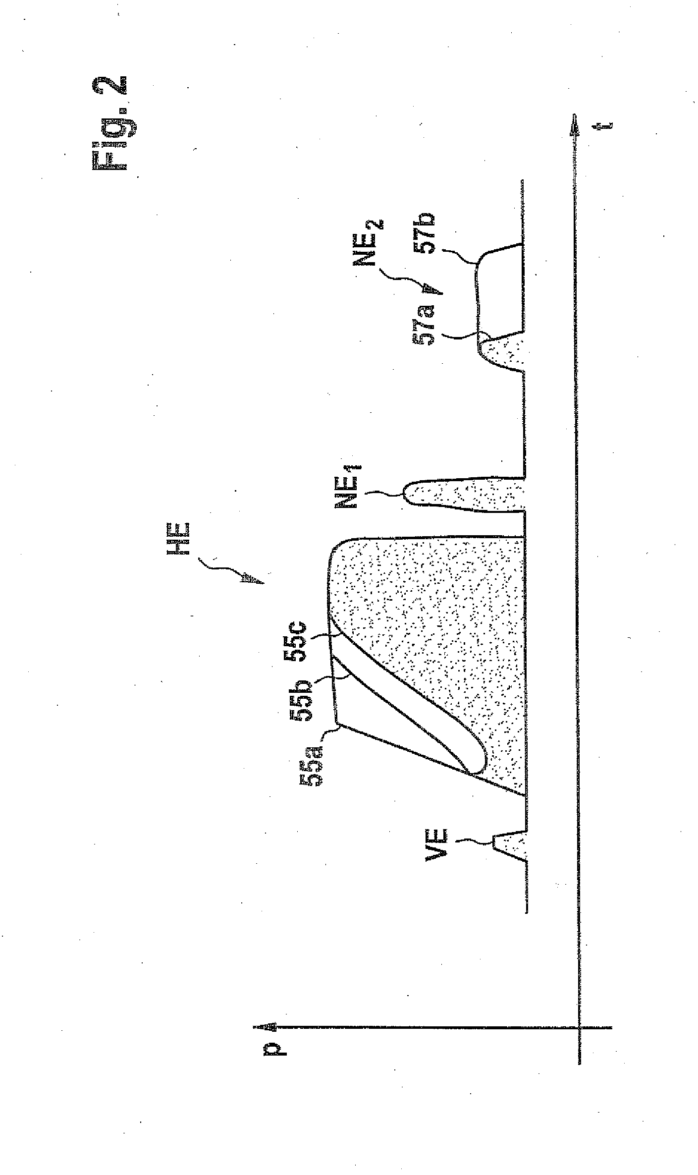
[0004]It is thus possible to optionally execute an injection with the pressure prevailing in the rail or to further increase the pressure prevailing in the rail with the aid of the pressure booster. Intermediate forms of these two operating
modes are also possible, thus making it possible with the aid of the injector according to the invention to shape the injection curve within a broad range.
[0005]Another
advantage of the invention is that a leakage in the region of the
nozzle needle only occurs at times in which the nozzle needle is open. But at these times, the leakage is not problematic.
[0006]Since the pressure booster exerts the maximum possible
injection pressure on only very few of the components of the injector, it is possible to select a more reasonably priced construction of the injector. This also extends the service life of components not subjected to the maximum injection pressure.
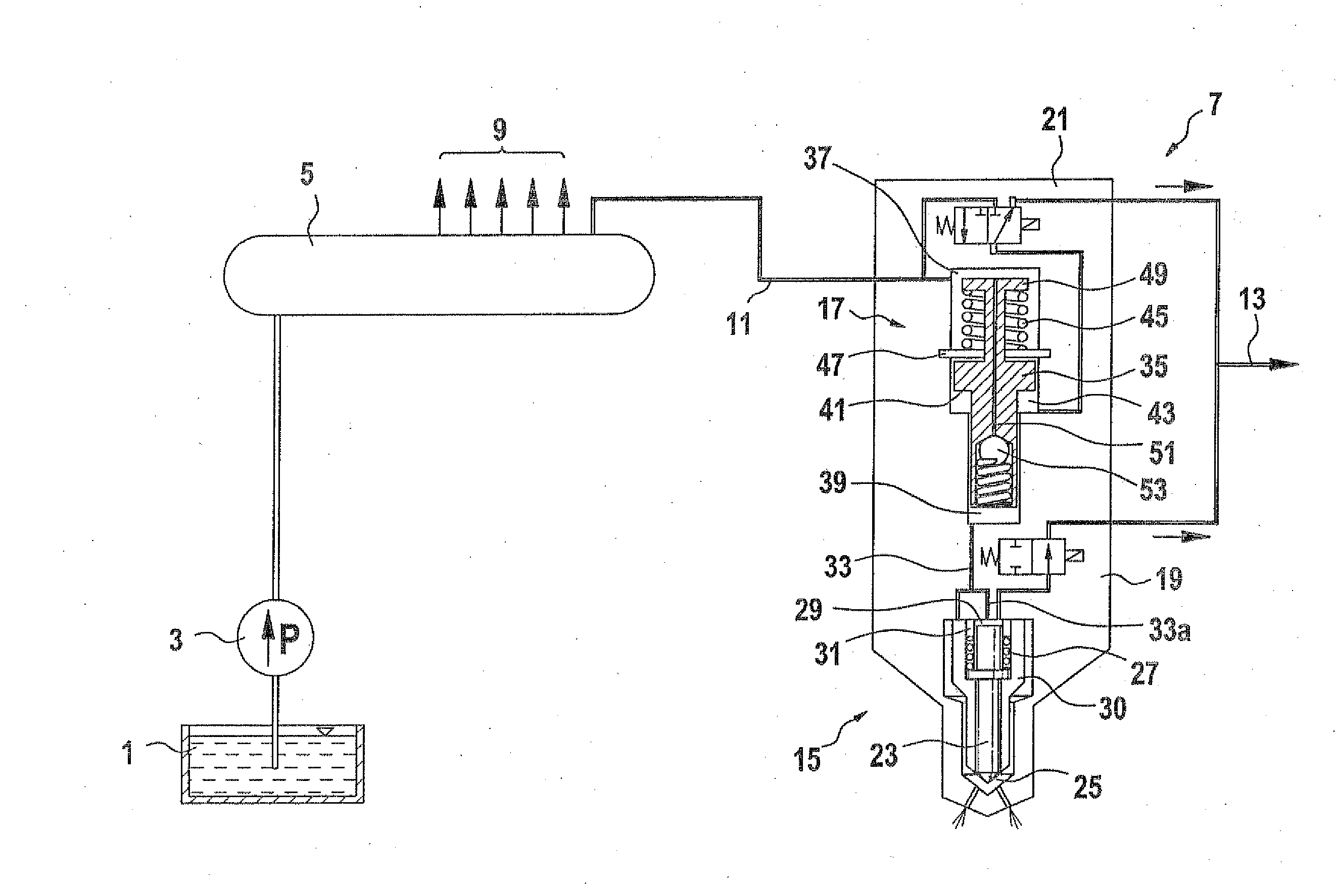
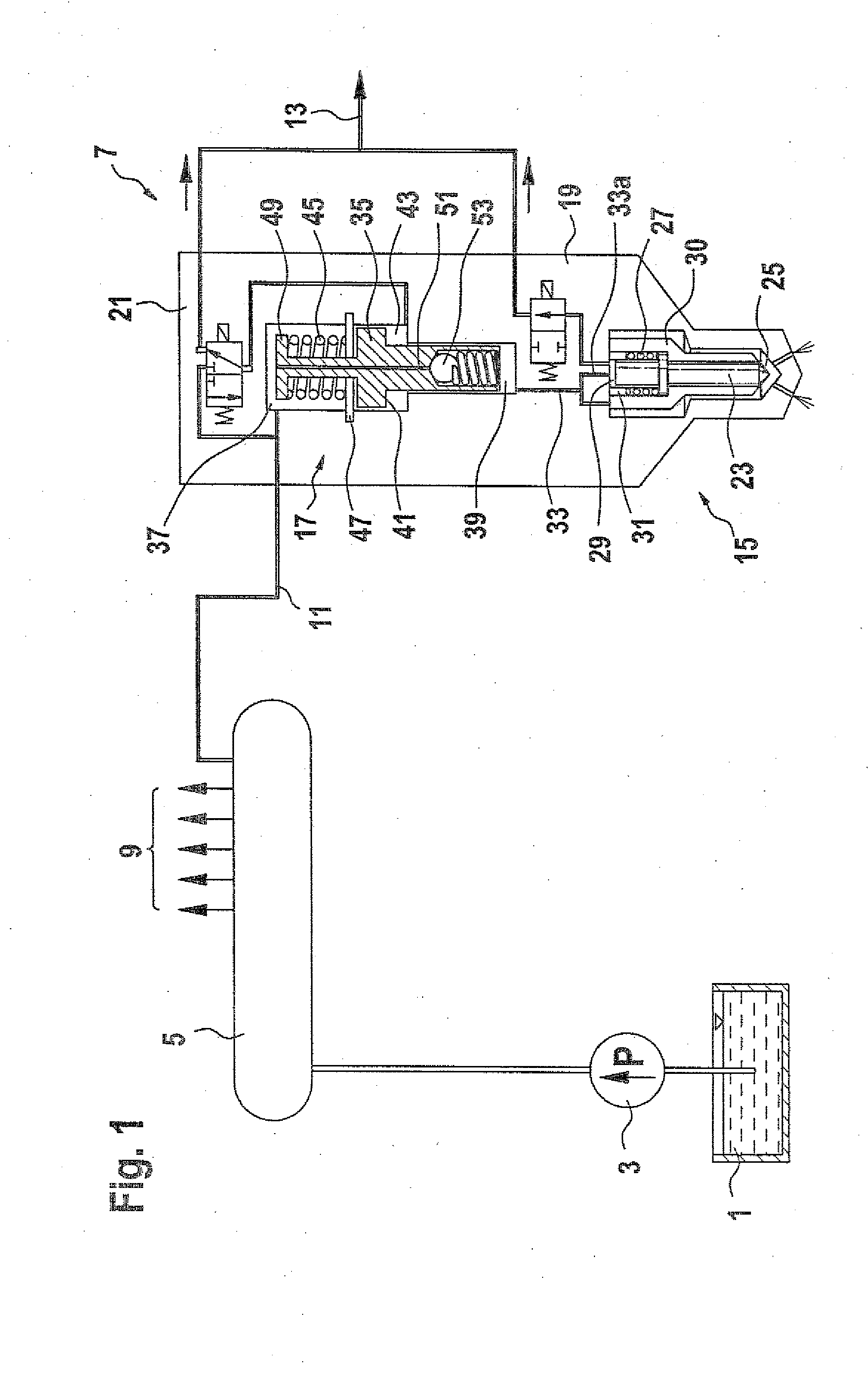
[0007]The pressure booster advantageously has a booster
piston that can move in a bore and whose end surfaces each delimit a pressure chamber; a first, larger end surface of the booster
piston delimits a first pressure chamber connected to the high-pressure connection, a second, small end surface at the opposite end of the pressure booster
piston delimits a second pressure chamber connected to the pressure shoulder and control chamber, and a
hydraulic connection equipped with a first
check valve is provided between the first pressure chamber and the second pressure chamber.
[0008]In this embodiment of the pressure booster, it is possible for fuel to flow from the first pressure chamber into the second pressure chamber, whereas the
check valve prevents fuel from flowing out of the second pressure chamber and back into the first pressure chamber. This makes it easily possible to act on the control chamber and the pressure shoulder with fuel that is only at the pressure prevailing in the rail.
[0009]It is particularly advantageous if the
hydraulic connection is embodied in the form of a longitudinal bore in the booster piston. The essential reason for this is the simple manufacture and the fact that no additional lines need to be sealed.
[0010]In a particularly compact design, the first
check valve is also situated in the booster piston. It is thus possible, once it has been preinstalled in the booster piston, to test the first check valve outside of the actual injector and thus to set it to the desired opening pressure.
[0011]In another advantageous embodiment of the pressure booster according to the invention, a cross-sectional change in the booster piston and a shoulder in a housing of the pressure booster delimit a relief chamber and the relief chamber can be optionally connected either to the return or to the high-pressure connection. When the relief chamber is hydraulically connected to the return, the booster piston can move as soon as the first pressure chamber is acted on with pressure from the rail and can thus execute a pressure boosting.
[0012]As soon as the relief chamber is hydraulically connected to the high-pressure connection, the forces acting on the booster piston from the relief chamber and the first pressure chamber equalize to such an extent that the pressure booster is not active.
[0013]The switching on and off of the pressure booster is advantageously carried out with the aid of a second control valve, which optionally connects the relief chamber to either the return or the high-pressure connection.
[0014]The pressure booster is advantageously provided with a return spring that exerts a return force on the booster piston in the direction toward the first pressure chamber. As a result, after the injection is executed, the booster piston returns to its original position and fuel displaced from the second pressure chamber is replenished by the return motion of the booster piston.
[0014]The pressure booster is advantageously provided with a return spring that exerts a return force on the booster piston in the direction toward the first pressure chamber. As a result, after the injection is executed, the booster piston returns to its original position and fuel displaced from the second pressure chamber is replenished by the return motion of the booster piston.
[0016]With the aid of the method according to the invention, it is possible to shape the curve of an injection within a broad range, thus enabling further improvements with regard to fuel consumption, emissions behavior, and
noise generation.


