
Heat exchanger for exhaust gas cooling; method for operating a heat exchanger; system with a heat exchanger for exhaust gas cooling

a heat exchanger and exhaust gas technology, applied in the field of heat exchangers, can solve the problems of decreasing the associated performance of the heat exchanger in continuous operation, and achieve the effect of preventing the fouling of the heat exchanger

Inactive Publication Date: 2008-10-30
BEHR GMBH & CO KG
View PDF9 Cites 81 Cited by
  • Summary
  • Abstract
  • Description
  • Claims
  • Application Information

AI Technical Summary

Benefits of technology

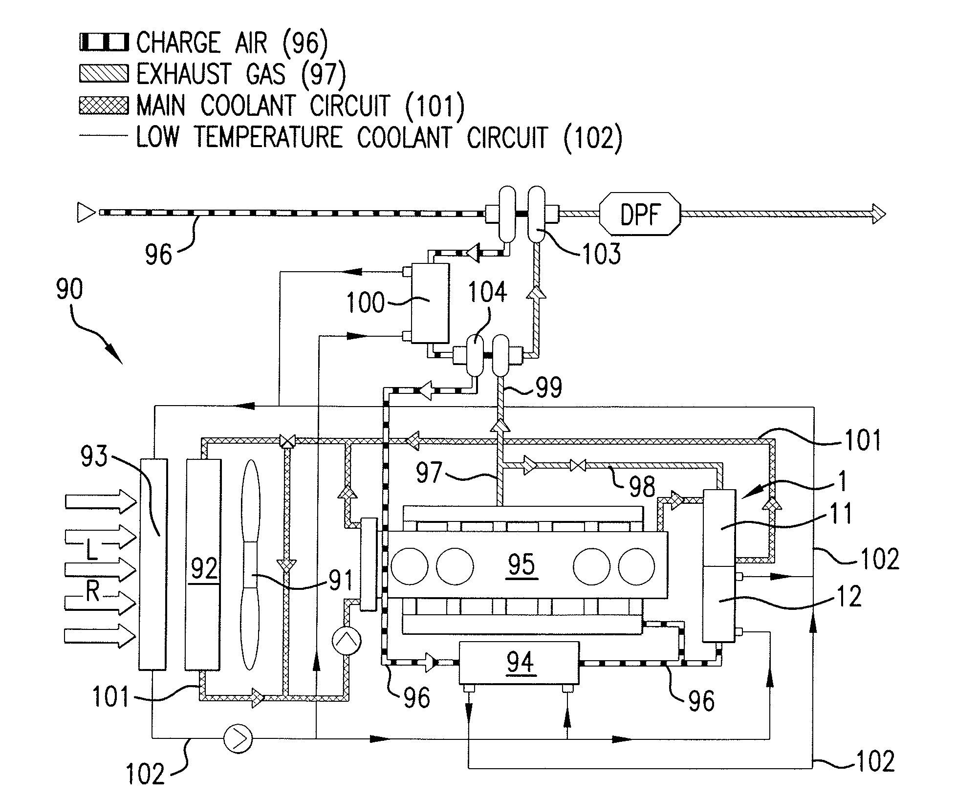
[0009]The problem of the present invention is to optimize a heat exchanger of the type mentioned above with regard to overall installation space and costs. In particular, the problem is to prevent the fouling of the heat exchanger by exhaust gas and the associated performance decrease of the heat exchanger in continuous operation.
[0037]Additionally, a method for operating the heat exchanger according to one of Claims 1-22 is proposed. The medium to be cooled, in particular, exhaust gas, condenses out at least water while flowing through the second heat exchanger in order to cleanse the second flow channel of fouling from the medium to be cooled. In this manner, fouling is particularly advantageously removed from the second partial heat exchanger, and performance is kept stable over the long term.

Problems solved by technology

In particular, the problem is to prevent the fouling of the heat exchanger by exhaust gas and the associated performance decrease of the heat exchanger in continuous operation.

Method used


Image

  • Heat exchanger for exhaust gas cooling; method for operating a heat exchanger; system with a heat exchanger for exhaust gas cooling
  • Heat exchanger for exhaust gas cooling; method for operating a heat exchanger; system with a heat exchanger for exhaust gas cooling
  • Heat exchanger for exhaust gas cooling; method for operating a heat exchanger; system with a heat exchanger for exhaust gas cooling

Examples


Embodiment Construction

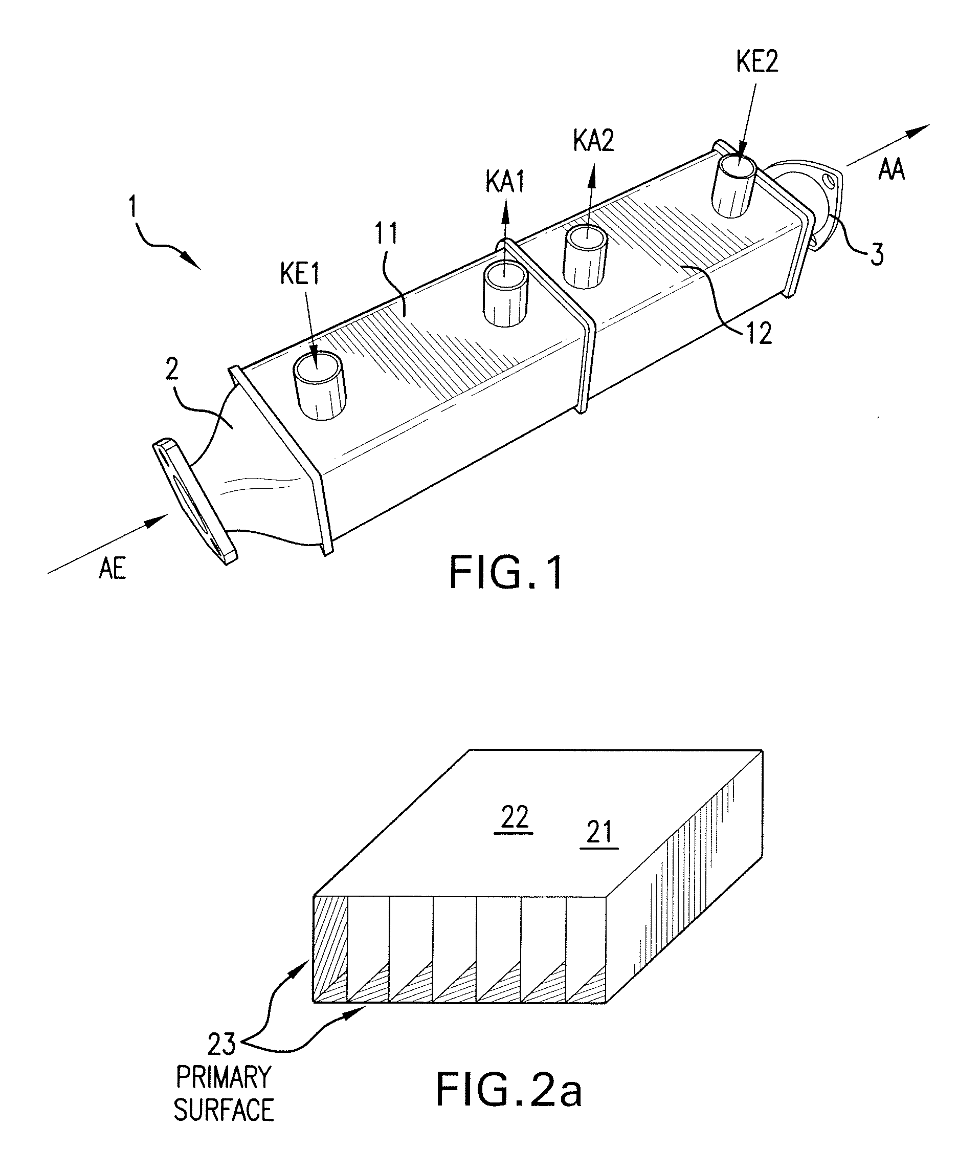
[0071]FIG. 1 shows a two-stage exhaust gas cooler 1. The exhaust gas cooler has a first partial heat exchanger 11 and a second partial heat exchanger 12.

[0072]Partial heat exchanger 11 has a housing of special steel of aluminum or of plastic. First coolant medium flows into partial heat exchanger 11 via a coolant inlet KE1 and, in a first stage, cools the exhaust gas AE flowing in via the inlet diffuser. The coolant exits via outlet KA1. The already cooled exhaust gas flows farther into second partial heat exchanger 12, where it is farther cooled, and subsequently exits in direction AA via outlet diffuser 3. The second coolant, air or water, for example, flows via additional inlet EA2 into partial heat exchanger 12 and out via outlet EA. Second partial heat exchanger 12 has a housing of special steel of aluminum, or of plastic.

[0073]FIG. 2a shows a cutout of first or second flow channel 21, 22 with a first heat transfer surface 23.

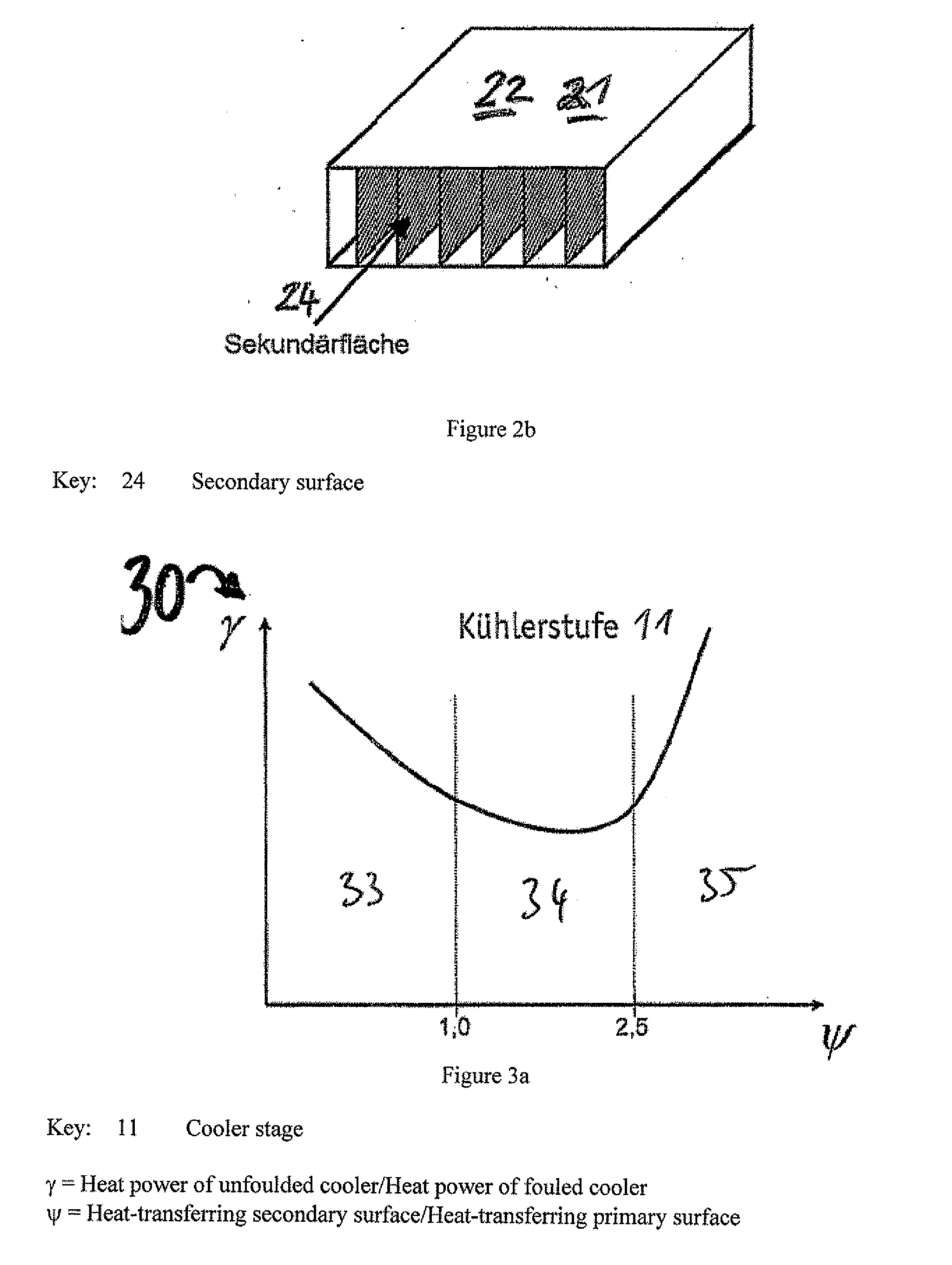
[0074]FIG. 2b shows a cutout of first or second flow...


PUM


Abstract

A heat exchanger, in particular for cooling the exhaust of a motor vehicle internal combustion engine, is disclosed, the heat exchanger comprising a first partial heat exchanger with at least one first flow channel through which a medium to be cooled is to flow and at least one third flow channel through which a first coolant is to flow, at least one second partial heat exchanger with at least one second flow channel through which a medium to be cooled is to flow and at least one fourth flow channel through which a second coolant is to flow, wherein the at least one first flow channel and the at least one second flow channel are fluidly connected, and the at least one first flow channel and the at least one second flow channel have at least one first specific heat transfer surface and at least one second heat transfer surface, wherein second specific heat transfer surface area, divided by first specific heat transfer surface area, yields a quotient (ψ), the at least one first flow channel having a larger quotient (ψ) than second flow channel.

Description

[0001]The present invention relates to heat exchangers, more particularly, for cooling the exhaust gas of an internal combustion engine of a motor vehicle, with at least one flow channel through which a medium to be cooled is to flow, and at least one third flow channel through which a first coolant is to flow, at least one second partial heat exchanger with at least one second flow channel through which the medium to be cooled is to flow and with at least one fourth flow channel through which a second coolant is to flow, wherein the at least one first and the at least one second channel are fluidically connected, and the at least one first flow channel and the at least one second flow channel have at least one first specific heat transfer surface and at least one second specific heat transfer surface.[0002]The invention further relates to methods for operating the heat exchanger according to one of Claims 1-22.[0003]The present invention further relates to a system with at least on...

Claims


Application Information

Patent Timeline
IPC IPC(8): F28D15/00
CPCF02B29/0412F02M25/0701F02M25/0707F02M25/0727F02M25/0732F02M25/0737F28D7/0091F28D9/0093F28D21/0003F28F3/025F28F3/044F28F13/14Y02T10/121F02M26/05F02M26/23F02M26/24F02M26/32F02M26/50Y02T10/12
Inventor LUTZ, RAINERRUCKWIED, JENSIRMLER, KLAUSSCHMIDT, MICHAELFETZER, TOBIASPANTOW, EBERHARDGESKES, PETERPFISTER, FLORIAN
Owner BEHR GMBH & CO KG
Learn More