
Injection Device

a technology of injection device and needle cover, which is applied in the direction of inhalator, infusion needle, infusion syringe, etc., can solve the problems of inability to provide such a small compartment, inability to provide such a small space, and the production of the device is rather costly or manual handling of the needle cover, so as to achieve convenient handling and reduce the cost

Active Publication Date: 2008-10-23
SHL MEDICAL AG
View PDF2 Cites 161 Cited by
  • Summary
  • Abstract
  • Description
  • Claims
  • Application Information

AI Technical Summary

Benefits of technology

[0012]The aim of the present invention is to provide a delivery device that is easy and safe to handle, based on a method for designing various features and various combinations.
[0024]This could be achieved without reducing the overall functionality of the device. Rather on the contrary, since fewer components generally are needed for performing a number of functions, the interplay between components, and thus the dependency that each component in a chain or series is designed so that the desired function is obtained, is reduced.
[0025]In all a device with a freedom to design and create a high degree of robust functionality is obtained with a reduced number of components, whereby the manufacturing costs are kept at a low level, which in turn enables the device to be used for example in a single dose delivery device that is discarded after completed injection.

Problems solved by technology

For some types of medicament the dose to be delivered is so small that it is not practically possible to provide such a small compartment in the enclosure or to provide a device that is capable of expelling the content from such a small compartment.
The majority of these devices include either rather complex mechanisms, like the former document, that makes the production of the device rather costly or manually handled needle covers, like the latter document, with the risk that the person handling the device un-intentially injures himself on the needle.

Method used


Image

  • Injection Device
  • Injection Device
  • Injection Device

Examples


Embodiment Construction

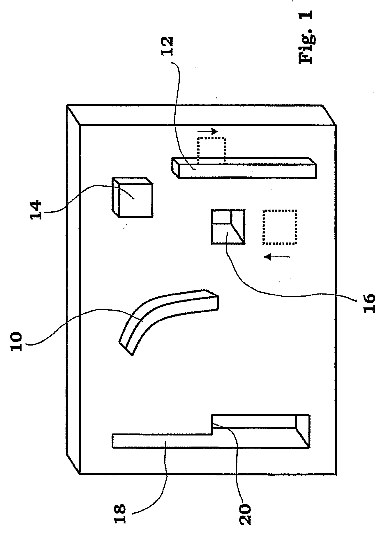
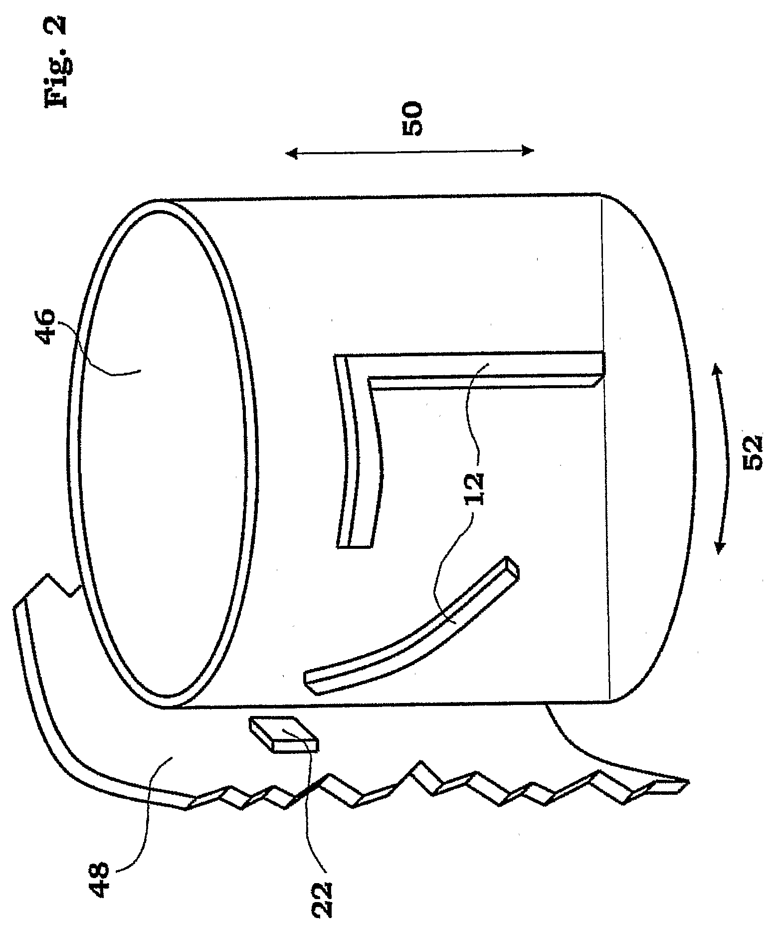
[0041]The general aspect of the invention will first be described in connection to the drawings, FIGS. 1-6.

[0042]The novel feature of the invention is the manner of controlling different functions of a device such as an injecting device. Depending on the degree of automation, such devices may have several functions included, which functions are more or less automated and may be working in series or in parallel with each other.

[0043]These functions may include priming of the medicament in liquid form prior to injection, mixing of medicament for multi-compartment ampoules or syringes, penetration of a needle into the body of a patient, injection of the medicament in the body of the patient, withdrawal of needle after injection, advancing of a needle shield for protection of the needle and subsequent locking of the needle shield. Further features may include setting of specific doses, delivery of specific doses, etc. The different features and functions entail co-operation and / co-actio...


PUM


Abstract

Injection device comprising a tubular elongated main body, a needle shield slidably arranged in said main body, a needle shield link slidably connected to said needle shield, a enclosure containing medicament arranged in said main body, a needle connected to said enclosure, a plunger operatively arranged to said enclosure for ejecting said medicament through said needle and arranged on its upper part with a number of outwardly extending stop members, spring means arranged to said plunger for operating said plunger, a dose activating means, a needle shield spring surrounding the needle shield link. The invention is characterised in that said injection device further comprises a first tubular member rotationally and slidably arranged inside said needle shield link, said tubular member comprises a number or ridges and protrusions on both its outer and inner surfaces, said ridges and protrusions on the outer surface of the tubular member co-operate with guide members arranged on the inner surface of said needle shield link, said ridges and protrusions on the inner surface of the tubular member co-operate with the outwardly extending stop members of the plunger that said injection device further comprises a second tubular member arranged inside said housing, arranged and designed with a number of ridges and protrusions on its inner and outer surfaces capable of setting and delivering a certain preset dose.

Description

TECHNICAL AREA[0001]The present invention relates to delivery devices such as injectors, mouth or nasal inhalers, powder or aerosol inhalers, nebulizers and the like.TECHNICAL BACKGROUND[0002]There are on the market a number of different delivery devices with varying degrees of automatic functions. The general trend is also that patients should be able to administer drugs and medicament by them selves, ie. without the need for trained staff to administer the drugs.[0003]There are however a number of aspects regarding delivery devices that are to be used by non-trained persons both in view of safety, both for the user and others that may come in contact with the device, as well as in view of handling and operation.[0004]For safety reasons many devices have been arranged with cover or protection means that are manually or automatically activated in order to protect persons from for example an injection needle, in particular after use.[0005]Many devices are provided with enclosures suc...

Claims


Application Information

Patent Timeline
IPC IPC(8): A61M5/32A61M5/315
CPCA61M5/2033A61M5/24A61M5/3146A61M5/31525A61M5/31553A61M5/3156A61M5/31563A61M5/3272A61M15/0065A61M2005/2013A61M5/19A61M5/3257A61M15/0066A61M5/31505A61M5/31586A61M5/3202
Inventor OLSON, STEPHAN
Owner SHL MEDICAL AG
Learn More