
Gas turbine engine with integrated abradable seal and mount plate

Inactive Publication Date: 2008-10-23
UNITED TECH CORP
View PDF17 Cites 27 Cited by
  • Summary
  • Abstract
  • Description
  • Claims
  • Application Information

AI Technical Summary

Benefits of technology

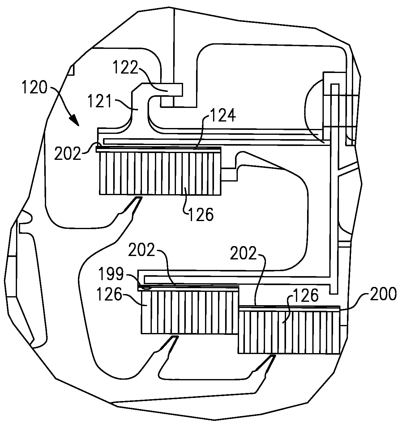
[0006]In a disclosed embodiment of this invention, an open cell structure of an abradable land is formed integrally with a closed mount plate. The closed plate is brazed to a mount structure, but the open cell structure is protected. The open cel

Problems solved by technology

The design of gas turbine engines includes a good deal of effort to reduce leakage in the turbine section.
In some instances, the wicked portion is beyond manufacturing tolerance and must be repaired; this adds significant cost and time to the manufacturing process.
The wicked portion also adds to the radial space requirements of the seal, which increases the overall size and weight of the engine.

Method used


Image

  • Gas turbine engine with integrated abradable seal and mount plate
  • Gas turbine engine with integrated abradable seal and mount plate
  • Gas turbine engine with integrated abradable seal and mount plate

Examples


Embodiment Construction

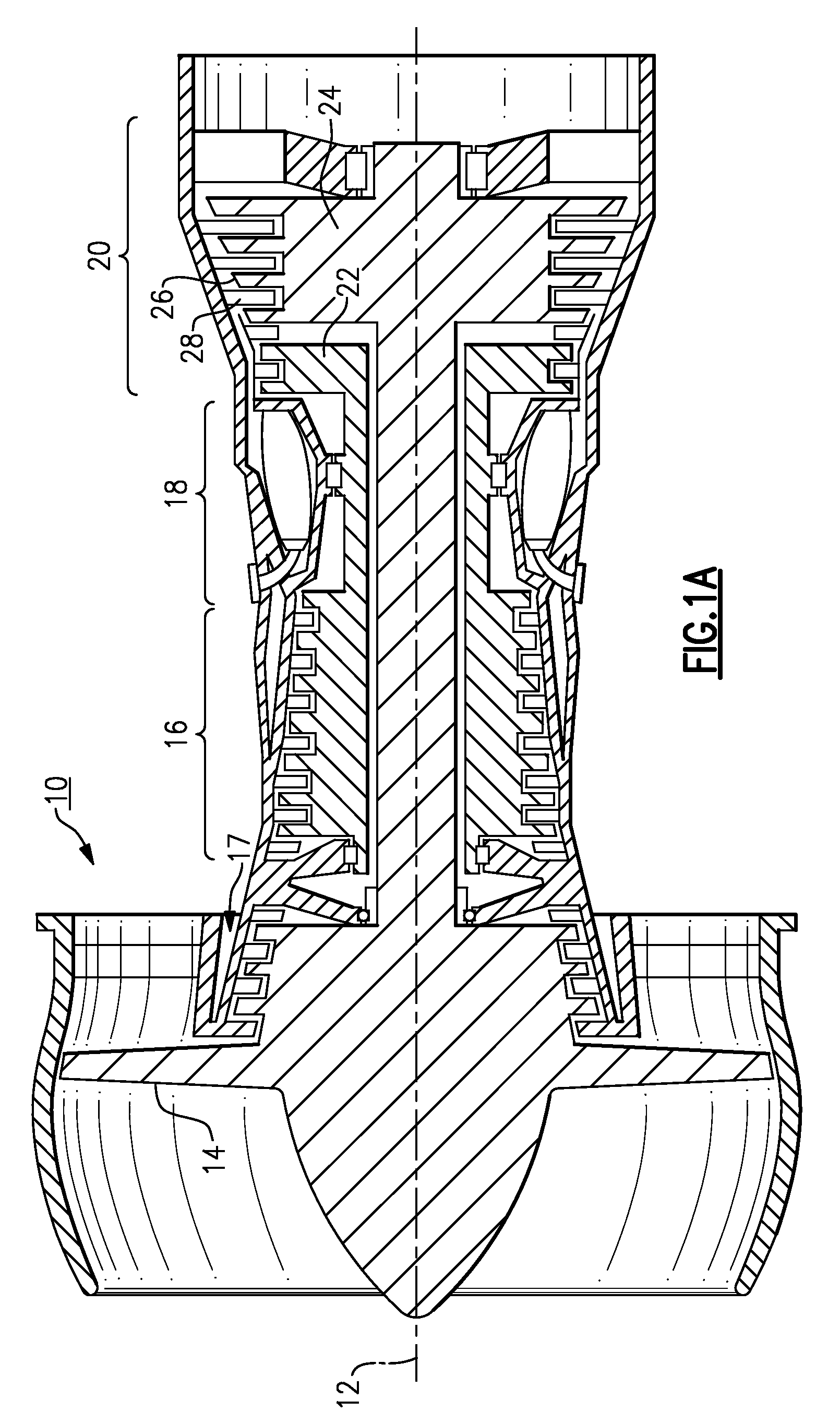
[0026]A gas turbine engine 10, such as a turbofan gas turbine engine, circumferentially disposed about an engine centerline, or axial centerline axis 12 is shown in FIG. 1A. The engine 10 includes a fan 14, compressors 16 and 17, a combustion section 18 and a turbine 20. As is well known in the art, air compressed in the compressor 16 is mixed with fuel which is burned in the combustion section 18 and expanded in turbine 20. The turbine 20 includes rotors 22 and 24, which rotate in response to the expansion, driving the compressors 16 and 17, and fan 14. The turbine 20 comprises alternating rows of rotary airfoils or blades 26 and static airfoils or vanes 28. This structure is shown somewhat schematically in FIG. 1. While one engine type is shown, this application extends to any gas turbine architecture, for any application.

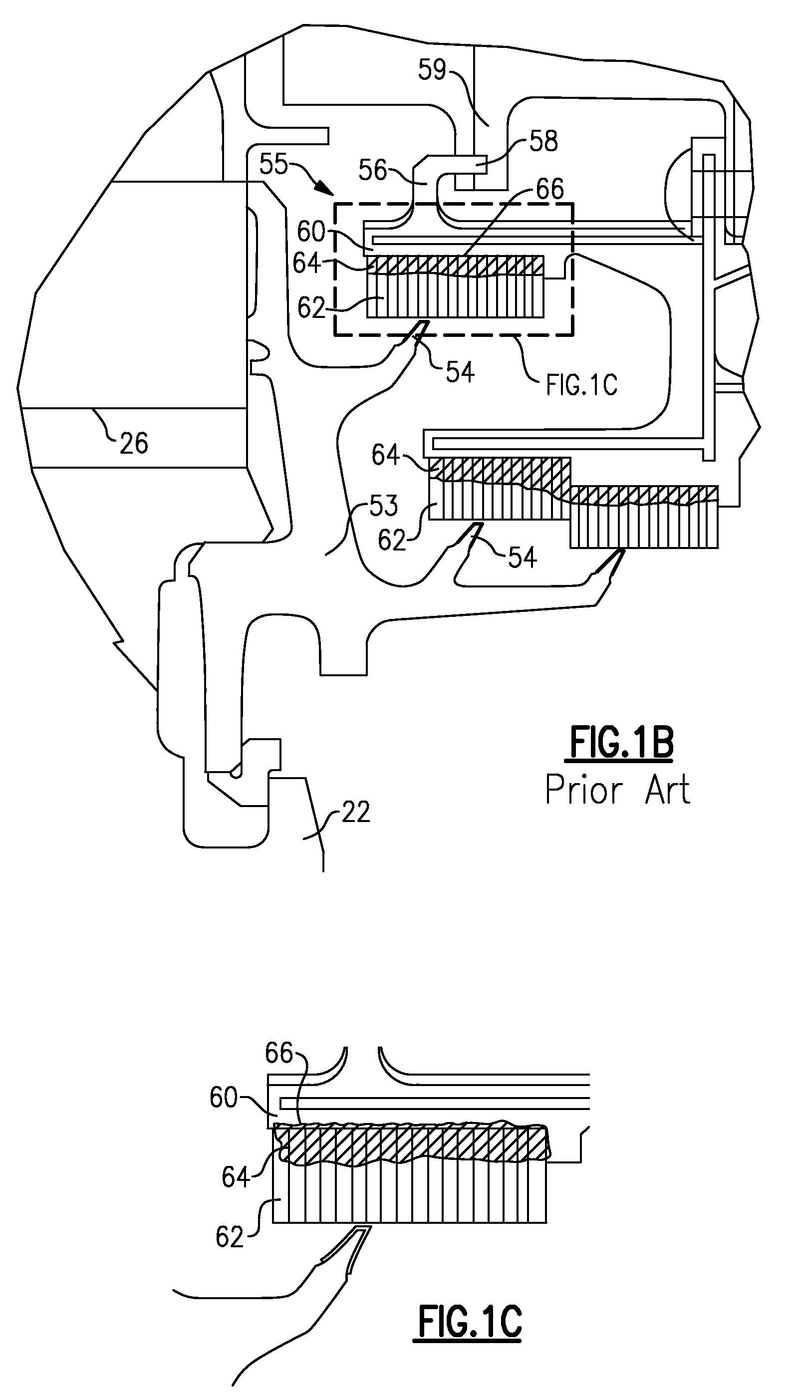
[0027]As shown in FIG. 1B, the rotor blades 26 and rotor 22 (or 24) also carry a cover plate seal 53. The cover plate seal rotates, and carries knife edge runner...


PUM


Abstract

An abradable sealing land for a gas turbine engine includes a mount plate and an open cell portion which is to be abraded. Both portions are formed integrally from a single piece of material.

Description

BACKGROUND OF THE INVENTION[0001]This application relates to a gas turbine engine, wherein OPEN CELL seal material is formed integrally with a closed mount plate.[0002]Gas turbine engines are known, and typically include a compression section receiving and compressing air. The compressed air is delivered downstream into a combustion section. The air is mixed with fuel in the combustion section and burned. Products of this combustion pass downstream over turbine rotors. The turbine rotors are driven to rotate, and create power.[0003]The design of gas turbine engines includes a good deal of effort to reduce leakage in the turbine section. The turbine section typically includes a plurality of rotors mounting a plurality of turbine blades, and which are the portions driven to rotate by the products of combustion. Seals on these rotors rotate in close proximity to static sealing structures to reduce leakage of pressurized fluid.[0004]In one widely used type of seal, the rotors carry knif...

Claims


Application Information

Patent Timeline
IPC IPC(8): F01D11/12F16J15/453
CPCF01D11/001F01D11/127F04D29/102F16J15/444F16J15/445F05D2240/55F05D2250/283
Inventor ALVANOS, IOANNIS
Owner UNITED TECH CORP
Learn More