
System and method for dectecting three-way attempts

a three-way call and detection system technology, applied in the field of three-way call detection, can solve the problems of many system control features that cannot be fully implemented, many of these systems are inaccurate, subject to both false positives and false negatives, and many frequencies, so as to reduce the number of three-way call attempts, eliminate or significantly reduce the number of false three-way calls detected

Active Publication Date: 2008-10-23
GLOBAL TELLINK
View PDF14 Cites 35 Cited by
  • Summary
  • Abstract
  • Description
  • Claims
  • Application Information

AI Technical Summary

Benefits of technology

[0015]The present invention embodies three-way call detection circuit for use with an existing telephone management system, and is designed to reduce the number of three-way call attempts not detected by current three-way call detection techniques as well as eliminate or significantly reduce the number of false three-way calls detected. The system of the present invention may be implemented in a variety of facilities including, but not limited to, penal institutions, mental institutions, nursing homes, rehabilitation centers, correctional facilities, government agencies, private and public business, and the like.
[0019]It has been shown that in certain instances a user can circumvent current three-way call detection systems by “covering up,”“masking,” or otherwise hiding a three-way call attempt by creating a constant or continuous noise (e.g., a constant hum or a constant hiss) while the three-way call is being attempted. Prior art systems are not designed to nor are they capable of detecting such a continuous noise. Thus, users of prior art systems can bypass the system simply creating continuous noise during a three-way call attempt.
[0021]The present invention further provides an improved method of monitoring for such a click. According to the present invention, a pulse is a click indicative of a three-way call attempt if the phases of the frequency components that comprise the pulse have a common group delay (i.e., each component has the same, or approximately the same phase delay). A click is comprised of many components all of which are generated at nearly the same instant in time. Thus, in accordance with the present invention, any of the components that comprise the pulse can be analyzed to determine if the pulse is indicative of a three-way call click (i.e., the invention does not require the filtering or analysis of one specific band or range of frequencies).
[0030]First, the phases computed by the FFT are preferably “unwrapped” (i.e., converted from a range of −π to π to a larger range to smooth out artifacts that result from the FFT calculation). The phase should be unwrapped because, although the FFT calculates a phase for each component, the sinusoidal nature of the output of the FFT results in a calculated phase that ranges from −π to π. If the real phase extends beyond this range, large jumps in phase may appear to exist between components when the calculated phrase “wraps around” the −π to π range. Therefore, phase unwrapping operates to correct these phase-jumping artifacts by adding multiples of + / −2π when absolute jumps between consecutive phases are greater than a predefined tolerance (e.g., π). The resulting unwrapped phases are thus smoother and devoid of artificial jumps.
[0037]If a pulse is having these characteristics is detected, then the FFT of the pulse signal is calculated, and the phase is analyzed as discussed above. Of course, the system may be used with other filters and three-way call detect methods to further increase accuracy.
[0044]Furthermore, it is an object of the invention to accurately detect three-way call attempts and respond with a designated action (e.g., disconnect, flag, record, monitor, etc.).

Problems solved by technology

Without such monitoring, many of the system's control features of a telecommunications system can be rendered ineffective.
Many of these systems however, are inaccurate and subject to both false positives and false negatives.
Also, many of these systems are effective only in certain types of telecommunications systems.
This system, by simply monitoring for a pulse composed of certain frequencies, is often inaccurate and cannot operate in digital systems.
Existing methods and systems are exceedingly inaccurate resulting in far too many false positive and false negative detections.

Method used


Image

  • System and method for dectecting three-way attempts
  • System and method for dectecting three-way attempts
  • System and method for dectecting three-way attempts

Examples


Embodiment Construction

[0060]As required, a detailed illustrative embodiment of the present invention is disclosed herein. However, techniques, systems and operating structures in accordance with the present invention may be embodied in a wide variety of forms and modes, some of which may be quite different from those in the disclosed embodiment. Consequently, the specific structural and functional details disclosed herein are merely representative, yet in that regard, they are deemed to afford the best embodiment for purposes of disclosure and to provide a basis for the claims herein, which define the scope of the present invention. The following presents a detailed description of the preferred embodiment of the present invention.

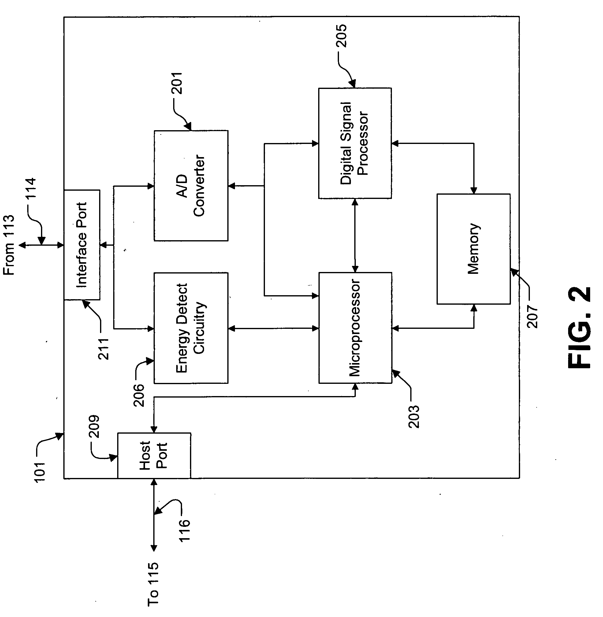
[0061]Referring first to FIG. 1, depicted is three-way call detection circuit 101 of the present invention configured to monitor telephone calls between an inmate or resident (calling from inmate telephone 103) and a called party (from called party telephone 111) in telecommunic...


PUM


Abstract

Disclosed is an improved three-way call detection system and method for use with a telephone management system. Specifically, a three-way call detection system and method for detecting continuous noise indicative of a an attempt to circumvent existing three-way call detection systems and methods. The continuous noise detection system and method may be used in conjunction with any existing three-way call detection system and method, including for example, a system and method that monitors the active communications of the telephone management system for pulses of energy indicative of a three-way call.

Description

CROSS-REFERENCE TO RELATED APPLICATIONS[0001]This is a continuation-in-part application of U.S. patent application Ser. No. 10 / 851,675, filed May 21, 2004, which is herein incorporated by reference in its entirety.FIELD OF THE INVENTION[0002]The present invention relates generally to the field of detecting three-way call attempts in controlled telecommunications systems. In particular, the invention relates to a system and method for preventing a user from circumventing the system's three-way call detection system or method simply by making a continuous noise. The system and method according to the present invention may be utilized with any existing three-way call detection system or method. For example, it may be used with the system and method for detecting a pulse of energy having components with a common phase delay. According to the present invention, a pulse with this characteristic is indicative of a three-way call attempt. The present invention preferably computes the Fast F...

Claims


Application Information

Patent Timeline
Patent Type & Authority Applications(United States)
IPC IPC(8): G06K9/46H04M1/00H04M1/82H04M3/00H04M3/22H04M3/38H04M3/56H04M3/58
CPCH04M1/82H04M3/2281H04M3/38H04M3/56H04M3/58
Inventor HODGE, STEVEKESTERSON, FREDOLDHAM, OLIVER
Owner GLOBAL TELLINK
Learn More