
Sealing device for joint section of robot and articulated robot having the same

a joint section and sealing device technology, applied in mechanical control devices, process and machine control, instruments, etc., can solve the problems of difficulty in preventing foreign matter from penetrating through the labyrinth seal into the wrist housing, and the sealing device may not sufficiently seal in the lubricant,

Active Publication Date: 2008-10-23
FANUC LTD
View PDF9 Cites 28 Cited by
  • Summary
  • Abstract
  • Description
  • Claims
  • Application Information

AI Technical Summary

Benefits of technology

[0008]It is an object of the present invention to provide a high-performance sealing device provided to a joint section of a robot, which can reliably prevent a lubricant or dust particles, retained or generated in a driving mechanism incorporated into the joint section, from leaking out, to the exterior of the joint section, and also prevent foreign matter in the external environment of the robot from penetrating into the interior of the joint section.
[0009]It is another object of the present invention to provide an articulated robot provided with a high-performance sealing device in a joint section, wherein the sealing device can reliably prevent a lubricant or dust particles, retained or generated in a driving mechanism incorporated into the joint section, from leaking out, to the exterior of the joint section, and also prevent foreign matter in the external environment of the robot from penetrating into the interior of the joint section, so that the articulated robot can be preferably used on manufacturing lines in which products are required to be free from contamination.

Problems solved by technology

However, if the lubricant in the driving mechanism passes through the grease seal, forming the inner seal portion of the overlapped seal portions, the above conventional sealing device may not sufficiently seal in the lubricant.
Further, since it is assumed that, in JP-A-63-22290, the robot is used in a clean room, in the case where foreign matter, such as dust particles, liquid droplets, etc., exist in the external environment of the robot, it may be difficult to prevent the foreign matter from penetrating through the labyrinth seal into the wrist housing.
Therefore, in the case of the articulated robot for handling products required to be free from contamination, even if the joint section is equipped with the sealing device described in JP-A-63-22290, it may be difficult to ensure sealing at a required level.

Method used


Image

  • Sealing device for joint section of robot and articulated robot having the same
  • Sealing device for joint section of robot and articulated robot having the same
  • Sealing device for joint section of robot and articulated robot having the same

Examples


Embodiment Construction

[0022]The embodiments of the present invention are described below in detail, with reference to the accompanying drawings. In the drawings, same or similar components are denoted by common reference numerals.

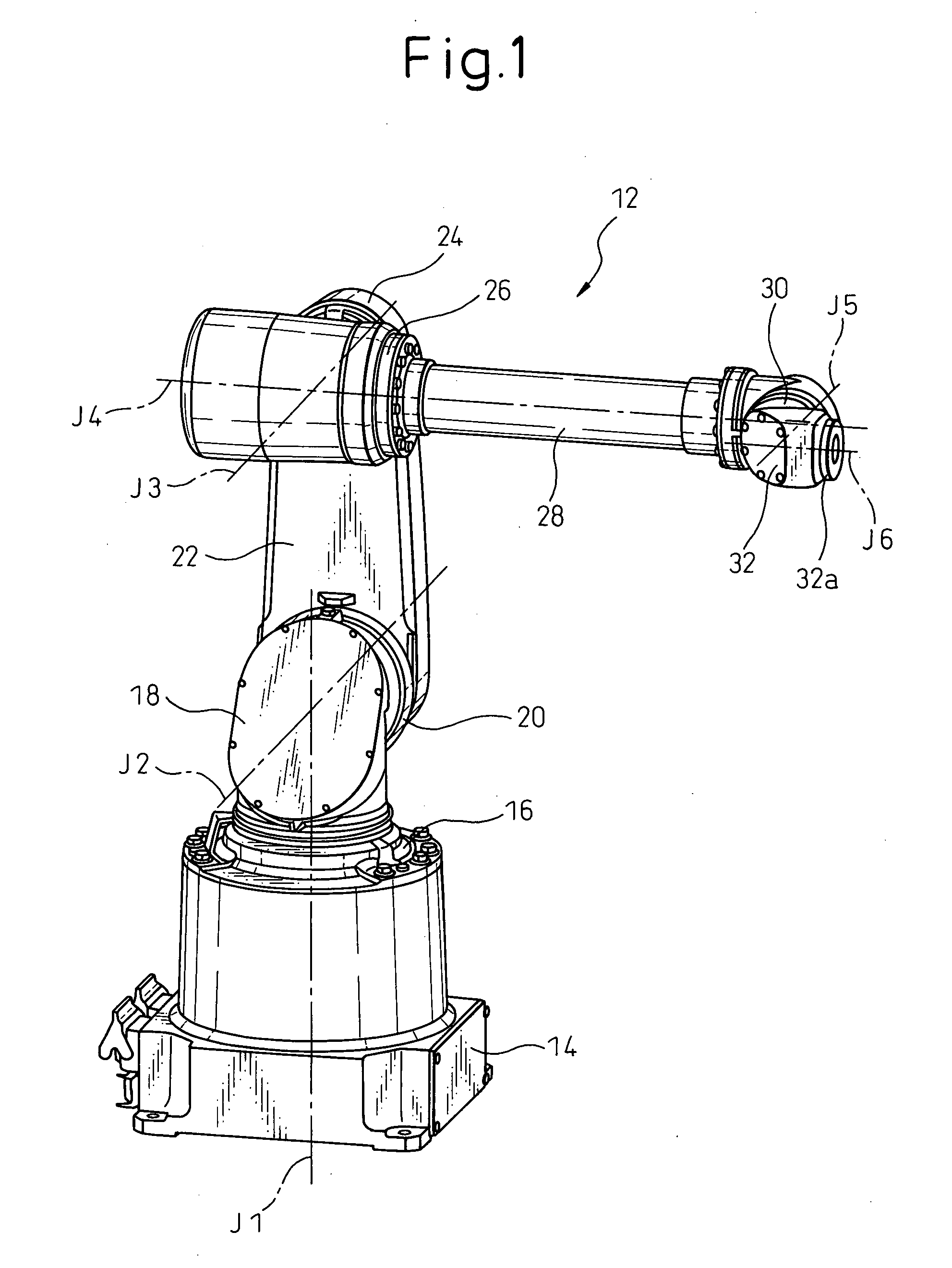
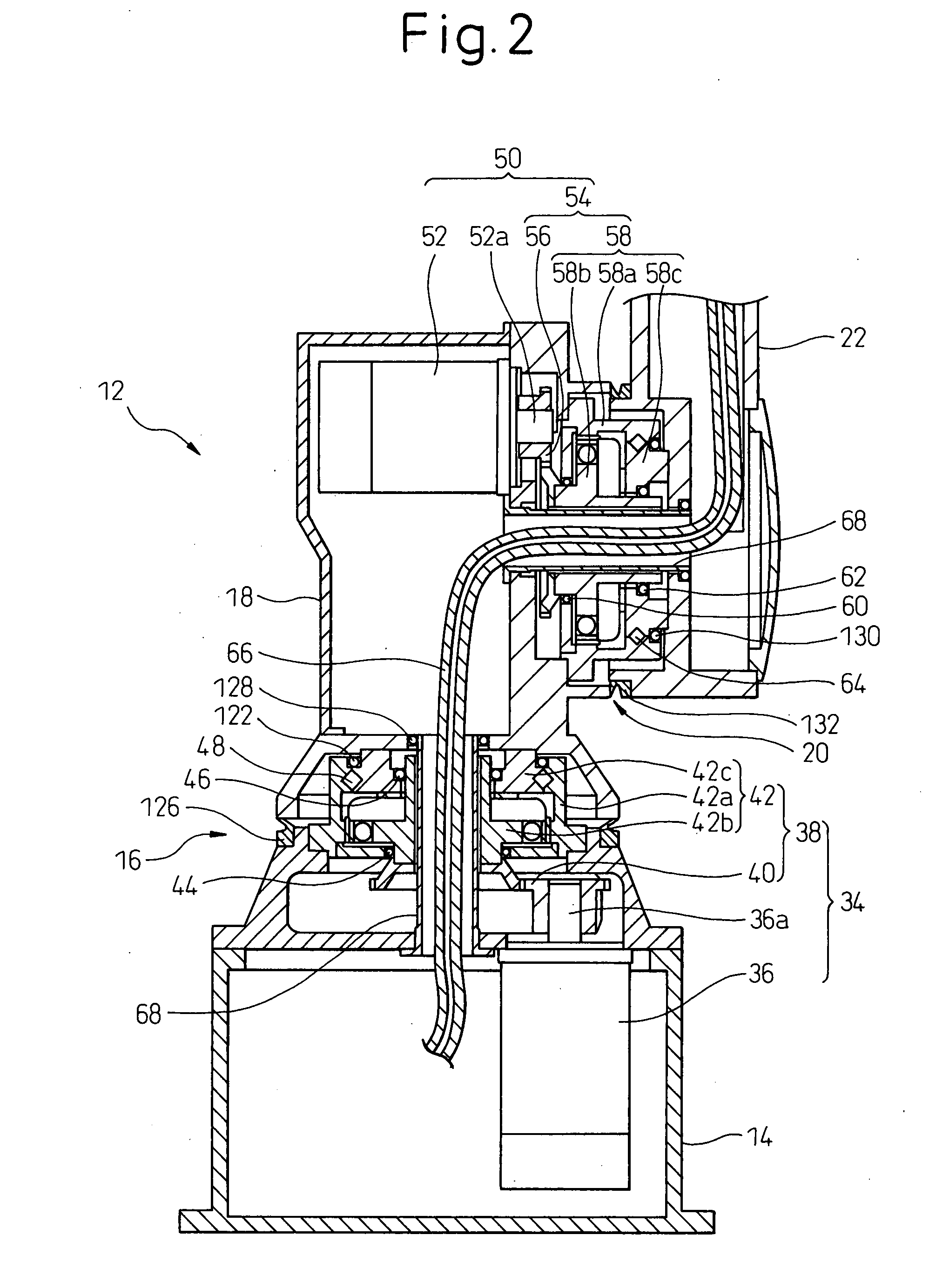
[0023]Referring to the drawings, FIG. 1 shows an articulated robot 12 (hereinafter simply referred to as a robot 12) according to an embodiment of the present invention and provided, in each joint section thereof, with a sealing device 10 according to an embodiment of the present invention; FIGS. 2 and 3 show the internal structures of joint sections of the robot 12; and FIGS. 4 and 5 show an enlarged view of the configurations of the sealing devices 10 provided to the joint sections of the robot 12. The robot 12 is shown to have a mechanical configuration of a 6-axis vertical articulated robot provided mainly with joint sections having a direct drive structure. However, the robot according to the present invention is not limited to this mechanical configuration.

[0024]As shown i...


PUM


Abstract

A sealing device provided to a joint section of a robot. The sealing device includes overlapped seal portions having a multi-stage configuration, provided for a driving mechanism incorporated into the joint section. The overlapped seal portions include a first seal portion including a first contact seal element sealing a first inter-member gap defined adjacent to a lubricant retaining section provided in the driving mechanism; and a second seal portion arranged outside the first seal portion and including a second contact seal element sealing a second inter-member gap defined in a circumferential wall of the joint section, the circumferential wall defining an accommodation space for accommodating the driving mechanism.

Description

BACKGROUND OF THE INVENTION[0001]1. Field of the Invention[0002]The present invention relates to a sealing device provided to a joint section of a robot. The present invention also relates to an articulated robot in which a joint section is equipped with a sealing device.[0003]2. Description of the Related Art[0004]Typically, in an articulated robot in which a driving mechanism for driving an arm or a wrist is incorporated into a joint section, in order to prevent a lubricant retained in the driving mechanism from leaking out, to the exterior of the joint section, an oil seal, as one type of a contact seal element, is provided in a relatively movable region of an output-end member of the driving mechanism (e.g., a bearing unit at the output side of a reduction gear unit). In particular, in certain applications where it is required to effectively prevent the environment of the robot or an objective workpiece to be operated by the robot from being contaminated due to the operation of ...

Claims


Application Information

Patent Timeline
IPC IPC(8): F16J15/16B25J17/00
CPCB25J19/0075Y10T74/20305Y10T74/20329Y10T74/20335
Inventor TAMURA, TOSHINARIKUREBAYASHI, HIDENORIAIZAWA, ATSUSHITANAKA, YASUYOSHIFUJIMOTO, KATSUMI
Owner FANUC LTD
Learn More