Eureka AIR delivers breakthrough ideas for toughest innovation challenges, trusted by R&D personnel around the world.

Short sleeve stent delivery catheter and methods

a stent and short sleeve technology, applied in the field of medical devices, can solve the problems the use of regular stents at bifurcation lesions with limited success rates, and the general production of straight tubular configurations, etc., to achieve the effect of reducing the risk of compromising the degree of patency of the main vessel and/or its branches, and facilitating catheter maneuvering within the patien

Inactive Publication Date: 2008-10-16
BOSTON SCI SCIMED INC
View PDF107 Cites 21 Cited by
  • Summary
  • Abstract
  • Description
  • Claims
  • Application Information

AI Technical Summary

Benefits of technology

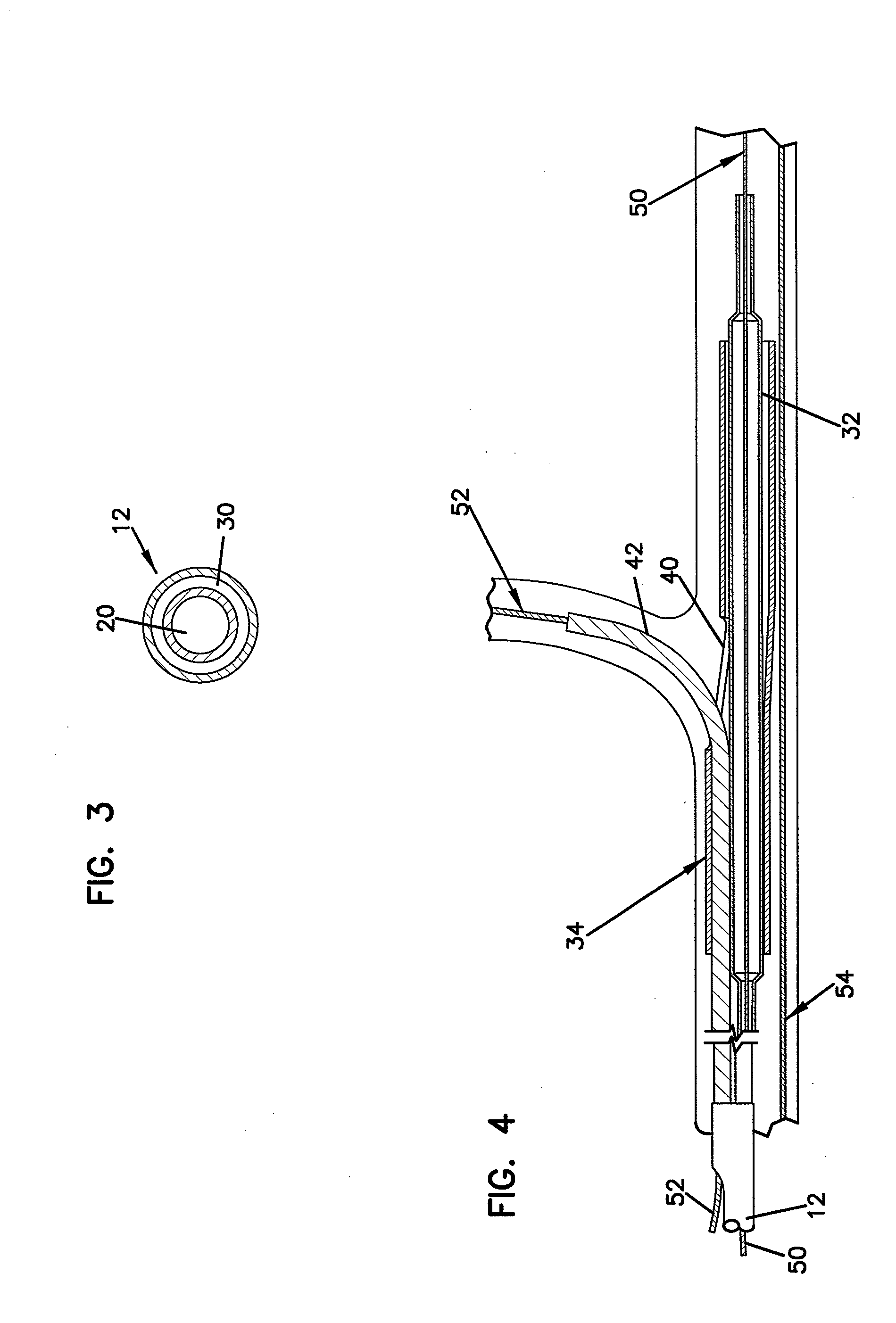
[0014]The use of the shortened side sheath provides a number of significant advantages. For example, shorter guidewires may be used to introduce the catheter. For example, guidewires ranging from about 100 cm to about 200 cm, and more preferably about 150 cm, may be used instead of conventional 300 cm guidewires. In this way, the catheter may be introduced and withdrawn from the patient by a single worker. Another significant feature is that the overall profile of the catheter is reduced to allow the catheter to be introduced into smaller guide catheters, thereby reducing trauma to the patient. For example, the catheter profile may be as low as about 4 to 7 French. The smaller profile also permits the catheter to be more easily maneuvered and rotated during introduction to the patient. For example, the reduction is profile permits the catheter to be introduced adjacent to a backup guidewire in the main vessel. If any wire crossing occurs between the back up guidewire and the branch vessel guidewire, the catheter may more easily be torqued by the physician to overcome the wire crossing.
[0015]In one aspect, the side sheath extends out of the side opening by a distance of at least about 0 cm to about 7 cm, and the catheter body has a length in the range from about 50 cm to about 150 cm. In another aspect, the catheter body further includes a balloon inflation lumen that is in fluid communication with the balloon. For example, the balloon inflation lumen may be coaxially disposed about the guidewire lumen. Conveniently, a hub may be coupled to the distal end to facilitate balloon inflation and guidewire introduction.
[0017]In one particular embodiment, the catheter body guidewire lumen terminates at the proximal end. Alternatively, the catheter body guidewire lumen may terminate in a side port within the catheter body at a location anywhere proximal to the balloon. For example, the side port may be located within about 1 cm to about 150 cm of the distal end. In this way, the overall profile of the catheter may be further reduced, with both the branch vessel guidewire and the main vessel guidewire may extend along the outside of the catheter body. Such a configuration further provides short or side exchange capabilities for the catheter. Reduction in profile size may be accomplished, for example, by constructing the catheter body from a tubular member, such as a hypo tube, surrounded by a nylon jacket. A stiffening mandrel may also be incorporated into a distal portion of the catheter body to provide torquing capabilities.
[0020]By advancing the catheter over a single guidewire, i.e., the branch vessel guidewire, the problem of wire crossing is significantly reduced. After the side sheath is near or into the branch vessel, the primary main guidewire may be further advanced into the main vessel.
[0021]In some cases, a physician will not want to lose wire placement and will therefore desired to maintain a guidewire within the main vessel at all times. In such cases, a secondary or back up main vessel guidewire may be inserted into the main vessel such that a distal end of the secondary main vessel guidewire passes beyond the ostium of the branch vessel prior to inserting the catheter over the branch vessel guidewire. Once the catheter is near the ostium and the primary main vessel guidewire has been advanced through the catheter, the secondary main vessel guidewire may be withdrawn prior to inflation of the balloon. If the branch vessel guidewire and the secondary main vessel guidewire cross, the catheter body may be torqued during insertion in order to overcome the wire crossing. The wire crossing may be overcome since the secondary main vessel guidewire runs along side of the catheter. Since the profile of the catheter may be relatively small, maneuvering of the catheter within the patient is also facilitated.

Problems solved by technology

Additionally, regular stents have been used at bifurcation lesions with limited success rates (Chevalier, B. et al.
One of the drawbacks of conventional stents is that they are generally produced in a straight tubular configuration.
The use of such stents to treat diseased vessels at or near a bifurcation (branch point) of a vessel may create a risk of compromising the degree of patency of the main vessel and / or its branches, or the bifurcation point and also limits the ability to insert a branch stent into the side branch if the result of treatment of the main, or branch vessel is suboptimal.
This condition may prevent the successful delivery of the catheter system by impeding its travel and, subsequently, the alignment of the stent's side opening with the ostium of the branch vessel.

Method used


Image

  • Short sleeve stent delivery catheter and methods
  • Short sleeve stent delivery catheter and methods
  • Short sleeve stent delivery catheter and methods

Examples


Embodiment Construction

[0035]In one aspect, the invention provides systems and methods for deploying stents at a vessel bifurcation such that a cell in the stent that is specifically designed to function as a branch aperture (referred to herein as a side hole of the stent) is in registry with the ostium of the branch vessel. Further, various techniques are provided for managing the guidewires over which the stents and stent delivery catheters are directed. More specifically, the invention provides techniques to help prevent the crossing of guidewires or to traverse crossed guidewires when introducing catheters used to deploy stents or other devices that require advancement over multiple guidewires, where it is important for the guidewires to be tangle free and parallel with respect to each other. In this way, the catheters may more easily be introduced to the diseased region.

[0036]The invention also provides techniques for reducing the profile of such delivery catheters, and to facilitate the introduction...


PUM


Abstract

A stent delivery catheter comprises a catheter body having a proximal end, a distal end, and a guidewire lumen extending from the distal end to at least part way between the proximal end and the distal end. A balloon is disposed over the catheter body near the distal end, and a stent is positioned over the balloon. The stent has a proximal end, a distal end, and a side opening between the proximal end and the distal end. A side sheath is coupled to the catheter body and has a proximal end, a distal end, and a guidewire lumen extending between the proximal end and the distal end. The proximal end of the side sheath is located between the proximal end of the catheter body and the balloon, and the side sheath exits out of the side opening of the stent.

Description

CROSS REFERENCE TO RELATED APPLICATIONS [0001]This application is a Continuation of U.S. patent application Ser. No. 09 / 860,744 filed on May 18, 2001, now U.S. Pat. No. 7,387,639, issued on Jun. 17, 2008 entitled SHORT SLEEVE STENT DELIVERY CATHETER AND METHODS, the disclosure of which is incorporated by reference herein in its entirety.[0002]U.S. Pat. No. 7,387,639 is a continuation-in-part of U.S. patent application Ser. No. 09 / 325,996, filed Jun. 4, 1999, entitled “CATHETER WITH SIDE SHEATH,” the disclosure of which is herein incorporated by reference. This application claims priority to Ser. No. 09 / 325,996 to the extent appropriate by law.[0003]U.S. Pat. No. 7,387,639 also is a continuation-in-part of U.S. patent application Ser. No. 09 / 455,299, filed Dec. 6, 1999, entitled “CATHETER WITH ATTACHED FLEXIBLE SIDE SHEATH,” the disclosure of which is herein incorporated by reference. This application claims priority to Ser. No. 09 / 455,299 to the extent appropriate by law.[0004]U.S. ...

Claims


Application Information

Patent Timeline
Patent Type & Authority Applications(United States)
IPC IPC(8): A61F2/84A61F2/06A61M25/12
CPCA61F2/856A61F2/954A61F2/958
Inventor BOURANG, HENRYVARDI, GIL M.WILLIAMS, ERICFARIABI, SEPEHRPATEL, UDAYANSAGASTEGUI, JAVIER
Owner BOSTON SCI SCIMED INC
Why Eureka
Eureka Blog
Learn More