
Microfluidic Liquid Stream Configuration System

a microfluidic and configuration system technology, applied in the field of microfluidic system architecture, can solve the problems of large size, high cost, and long time-consuming for those skilled in the art to find the solution to these problems

Inactive Publication Date: 2008-10-16
ZYMERA
View PDF9 Cites 30 Cited by
  • Summary
  • Abstract
  • Description
  • Claims
  • Application Information

AI Technical Summary

Problems solved by technology

In many of these applications, the pumps, power supplies, valves, motors, and other hardware needed to implement a complete system are much larger and more expensive than the microfluidic component.
Solutions to these problems have been long sought but prior developments have not taught or suggested any solutions and, thus, solutions to these problems have long eluded those skilled in the art.

Method used


Image

  • Microfluidic Liquid Stream Configuration System
  • Microfluidic Liquid Stream Configuration System
  • Microfluidic Liquid Stream Configuration System

Examples


Embodiment Construction

[0047]The following embodiments are described in sufficient detail to enable those skilled in the art to make and use the invention. It is to be understood that other embodiments would be evident based on the present disclosure, and that process or mechanical changes may be made without departing from the scope of the present invention.

[0048]In the following description, numerous specific details are given to provide a thorough understanding of the invention. However, it will be apparent that the invention may be practiced without these specific details. In order to avoid obscuring the present invention, some well-known circuits, system configurations, and process steps are not disclosed in detail. Likewise, the drawings showing embodiments of the system are semi-diagrammatic and not to scale and, particularly, some of the dimensions are for the clarity of presentation and are shown greatly exaggerated in the drawing FIGs. Where multiple embodiments are disclosed and described, havi...


PUM


Abstract

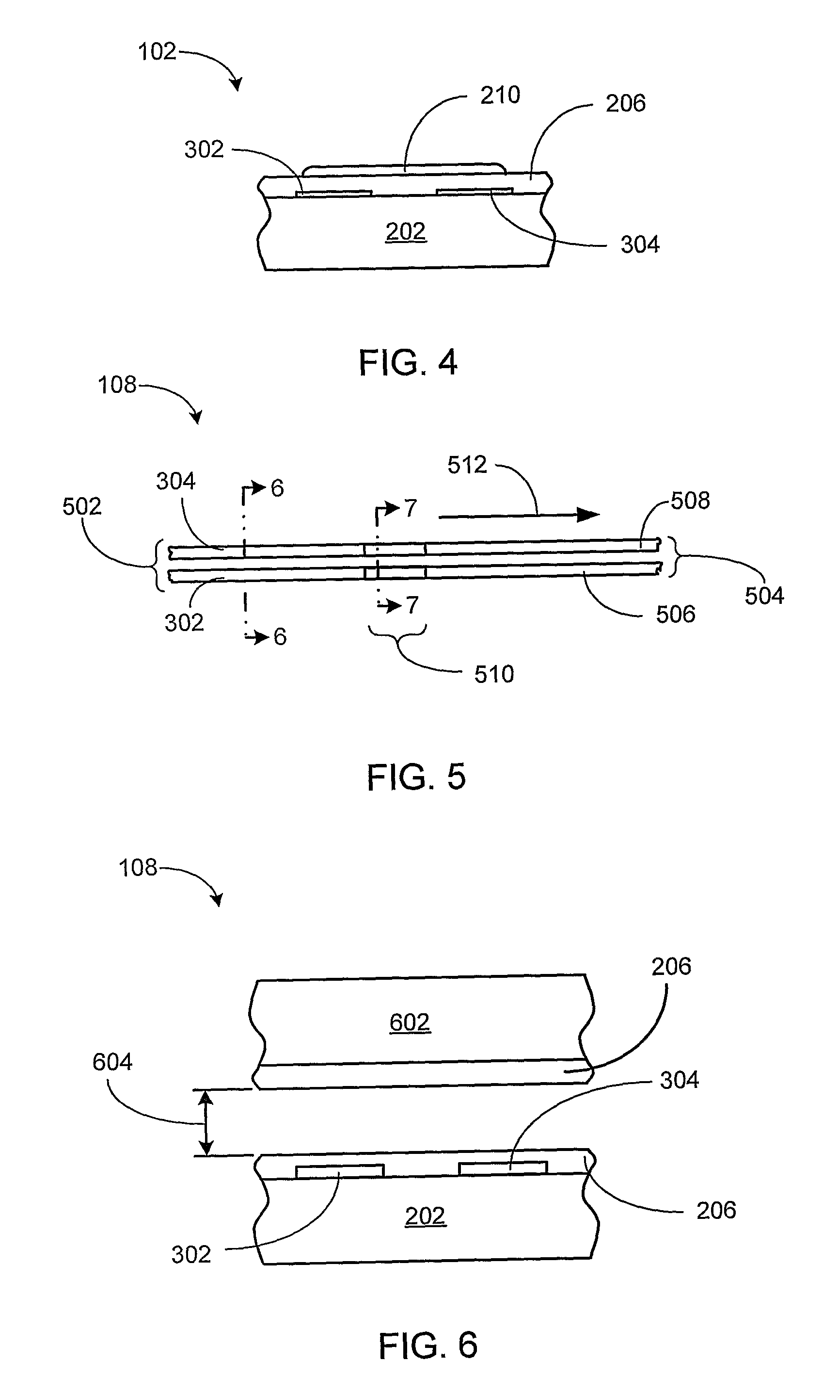
A microfluidic liquid stream configuration system is provided including providing a substrate; forming a first co-planar electrode and a second co-planar electrode on the substrate; applying a dielectric layer, with a controlled surface energy, on the first co-planar electrode and the second co-planar electrode; forming an input reservoir on the first co-planar electrode and a second co-planar electrode; supplying a liquid in the input reservoir for analysis; and imposing an electric field, an electric field gradient, or a combination thereof on the liquid for respectively driving surface charge or dipole moments in the liquid for configuring a liquid stream.

Description

CROSS-REFERENCE TO RELATED APPLICATION[0001]This application claims the benefit of U.S. Provisional Patent Application Ser. No. 60 / 596,015 filed 23 Aug. 2005.TECHNICAL FIELD[0002]The present invention relates generally to the electrically controlled movement of small liquid samples, and more particularly to a system of microfluidic system architecture for dynamic routing of a liquid stream.BACKGROUND ART[0003]There are clinical and analytical chemistry applications that require precise manipulation of small liquid samples. For example, the analysis of a whole blood specimen may require several manipulations including separation of erythrocytes, leukocytes, and platelets from plasma; dispensing the plasma to one or more reaction volumes; mixing reagents; incubating plasma and reagent mixtures; and performing optical or electrochemical measurement of the treated samples. In addition, advanced protocols may require separating different plasma proteins.[0004]Depending on the overall sys...

Claims


Application Information

Patent Timeline
IPC IPC(8): G01N27/00
CPCB01L3/50273B01L3/502738B01L3/502792B01L2300/0645B01L2300/069B01L2300/089B01L2400/0415B01L2400/0448B01L2400/06F04B19/006G01N33/4905
Inventor SOBEK, DANIELZENG, JUN
Owner ZYMERA
Learn More