Lining material and pipeline lining method

a technology of lining material and pipeline, which is applied in the direction of shaft lining, shaft equipment, mechanical equipment, etc., can solve the problems of reducing the ease of insertion and smooth insertion of pipeline, and reducing the product quality of lining material. , to achieve the effect of preventing stretching and damage to lining material, preventing easy and smooth insertion into pipeline, and preventing damage to lining

Active Publication Date: 2008-10-16
SHONAN GOSEI JUSHI SEISAKUSHO KK
View PDF16 Cites 7 Cited by
  • Summary
  • Abstract
  • Description
  • Claims
  • Application Information

AI Technical Summary

Benefits of technology

[0009]In the lining material of the present invention, the strip member imparts elasticity and rigidity to allow the trunk to be reinforced. Therefore, the lining material can be easily and smoothly inserted into a pipeline even where there is a plurality of sections bent at a right angle or close to a right angle, and it is possible to prevent the lining material from being stretched and damaged by forcible insertion. The lining material can be protected by the strip member during insertion, making it possible to prevent damage to the lining. The pipeline lining method of the present invention uses a lining material having a strip member of the present invention. Therefore, insertion of the lining material into a pipeline can be easily and smoothly performed, stretching and damage to the lining material can be prevented, and the time for lining work can be reduced.

Problems solved by technology

However, in the conventional insertion method for a lining material, insertion in pipelines is extremely difficult in sections that are bent at a right angle or close to a right angle.
Furthermore, with a drawing-in method, the contact resistance of the lining material increases as the bent sections increase, and the lining material therefore becomes heavier and is unable to be drawn in.
If drawing in continued forcibly, the lining material is stretched and damaged, which dramatically reduces the product quality of the lining material.

Method used


Image

  • Lining material and pipeline lining method
  • Lining material and pipeline lining method
  • Lining material and pipeline lining method

Examples


Embodiment Construction

[0017]The present invention will now be described in detail with reference to the embodiments shown in the accompanying drawings.

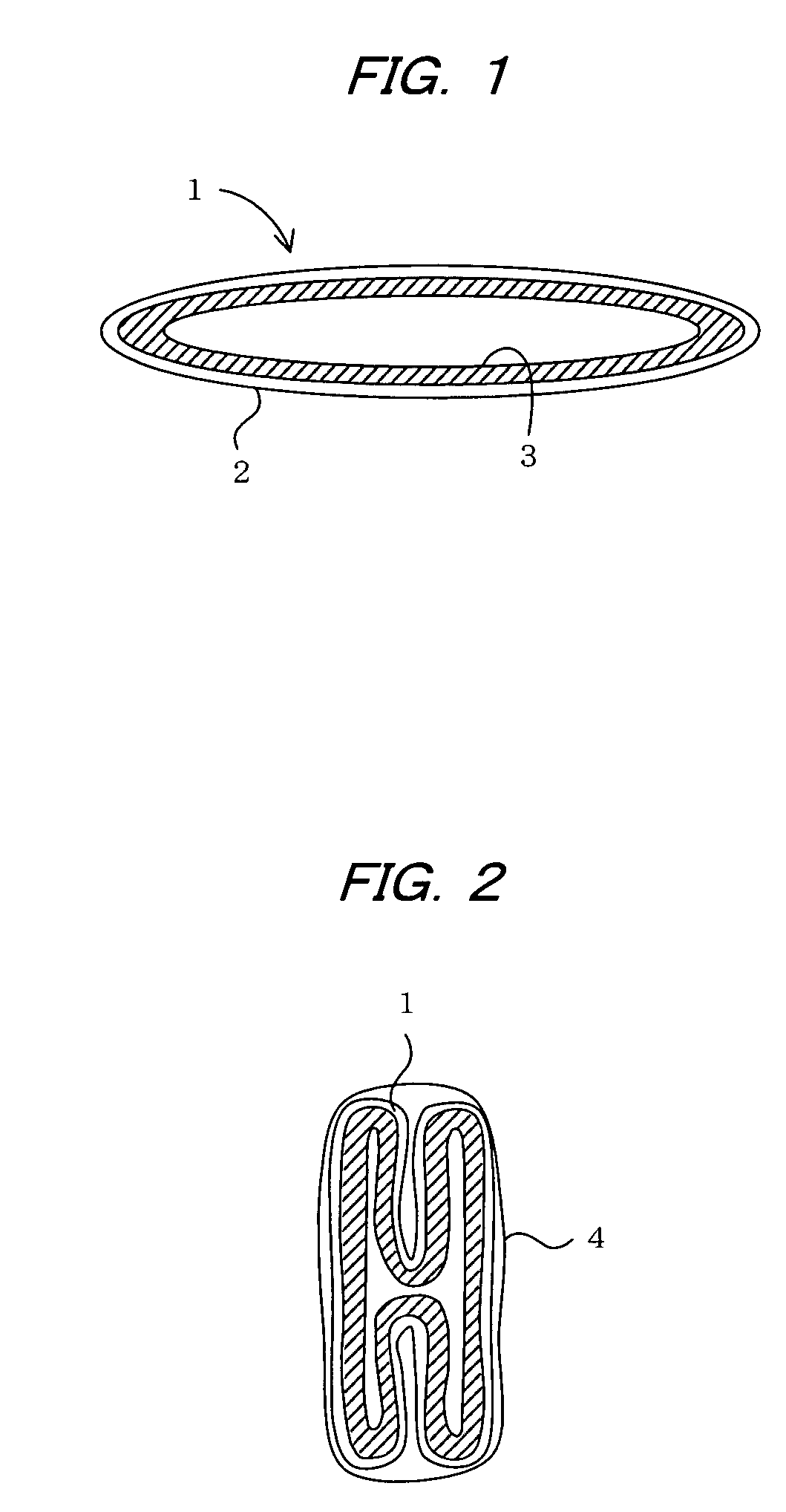
[0018]FIG. 1 shows a lining material used to repair pipelines. The lining material 1 is a flexible tubular material comprising a flexible cylindrical resin-absorbing material 3 of a non-woven fabric or the like whose exterior surface is covered by a flexible tube 2 of polyethylene or the like. The resin-absorbing material 3 is impregnated with an uncured liquid thermosetting resin.

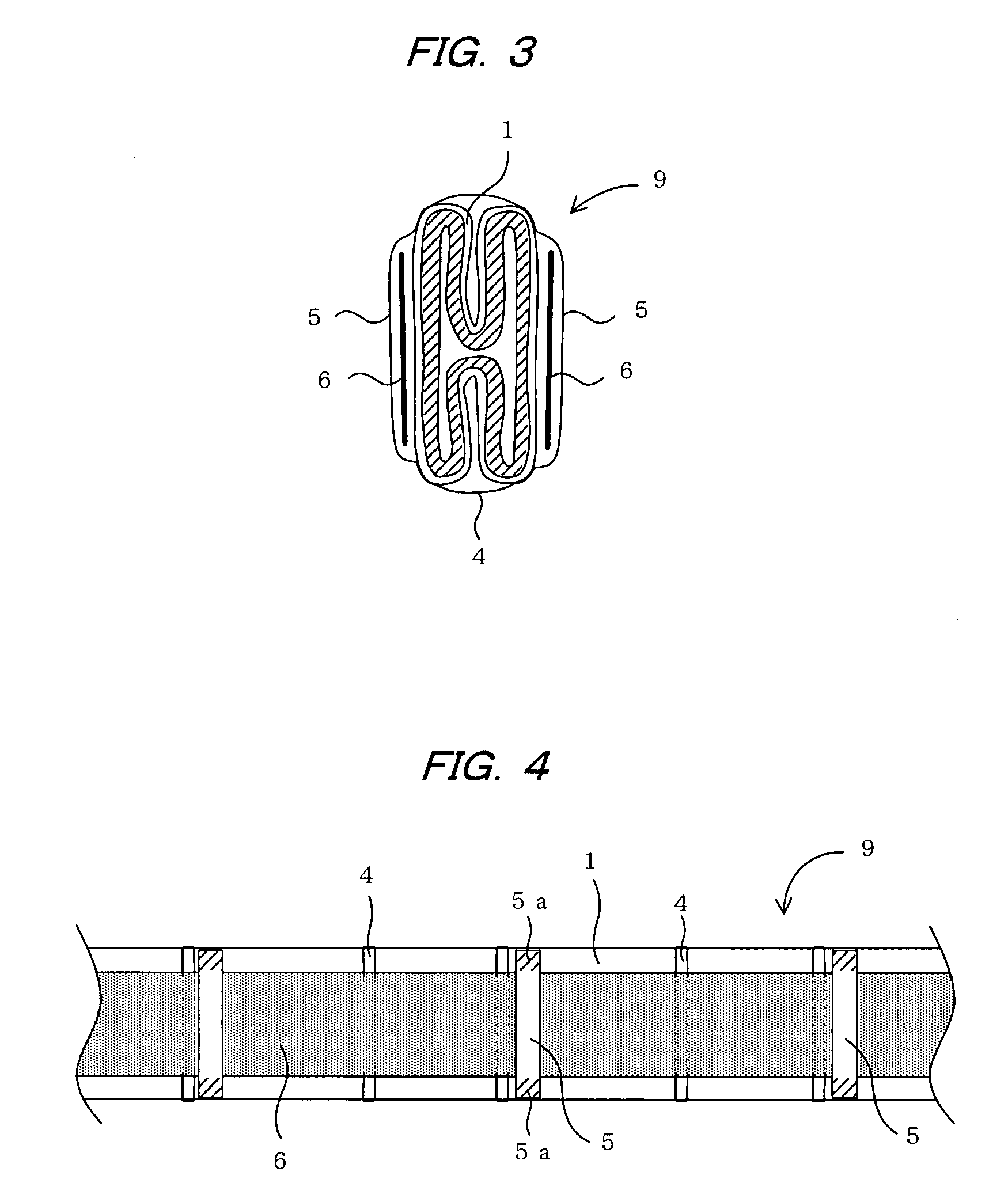
[0019]In the present embodiment, the lining material 1 is folded and bound so as to provide a reduced width, as shown in FIG. 2, and a steel belt 6 as shown in FIGS. 3 to 5 is removably attached to the folded lining material to provide a steel-belted lining material 9 (hereafter abbreviated as belted lining material) in order to facilitate the insertion of the lining material into the pipeline.

[0020]The steel belt 6 is elastic and rigid, imparts elasticity and rigidity to the lin...


PUM

PropertyMeasurementUnit
length L1aaaaaaaaaa
lengthaaaaaaaaaa
flexibleaaaaaaaaaa

Abstract

A flexible tubular lining material impregnated with a thermosetting resin is folded and bound with tape to provide a reduced width. Two steel belts are inserted into belt loops and are removably attached so as to sandwich the lining material. During pipeline lining work, first, the steel-belted lining material is inserted into a lateral pipe from the main pipe. The steel belts are then removed from the lining material so that the lining material may remain inside the pipeline. The steel belts are extracted from the pipeline, and the lining material is then made to expand via application of pressure from the inside. While kept in contact with the inner peripheral surface of the pipeline, the lining material is heated in order to cure the thermosetting resin thereof.

Description

BACKGROUND OF THE INVENTION[0001]1. Field of the Invention[0002]The present invention relates to a lining material used to line pipelines in order to repair an aged pipeline, and a pipeline lining method using the same.[0003]2. Description of the Prior Art[0004]When a communications pipe, gas pipe, sewer pipe, water pipe, electrical pipe, or other pipeline buried under ground has aged and a pipe in the pipeline is to be repaired without the pipe being removed from the ground, pipeline lining methods are used in which a tubular pipe lining material impregnated with a thermosetting resin is inserted into the pipeline by pushing or drawing, the lining material is heated while being expanded by air pressure or the like and pressed against an inner peripheral surface of the pipeline, and the thermosetting resin of the lining material is cured to line the pipeline. Air pressure is used to evert and insert the lining material into the pipeline (e.g., Japanese Laid-open Patent Application N...

Claims


Application Information

Patent Timeline
Patent Type & Authority Applications(United States)
IPC IPC(8): F16L11/00B08B9/027
CPCF16L55/1654F16L55/1656
Inventor TANAKA, FUMINORIFUJII, KENJI
Owner SHONAN GOSEI JUSHI SEISAKUSHO KK
Why Eureka
Try Eureka