Method and Device for Determining Defects in a Turbine Blade

a technology of turbine blades and defects, applied in the field of methods, can solve the problems of inability to investigate the roots affecting the reliability of components, and affecting the strength of components, so as to achieve reliable and fast results, no time-consuming and thus costly dismantling and installation of turbine blades, and the effect of determining the defects of turbine blades in the installed sta

Active Publication Date: 2008-10-16
SIEMENS ENERGY GLOBAL GMBH & CO KG
View PDF11 Cites 18 Cited by
  • Summary
  • Abstract
  • Description
  • Claims
  • Application Information

AI Technical Summary

Benefits of technology

[0022]The advantage of the invention can be seen in that, among other things, defects in turbine blades can be determined in the installed state. There is no time consuming and thus costly dismantling and installation of the turbine blades.
[0023]The proposed use of probes which are constructed as phased arrays enables the direction of the radiated ultrasound or the direction from which the ultrasound can be received to be changed.
[0024]As a result of this method, it is possible, for example, to perform reliable and fast analyses in an expected fault area of turbine blade roots. Cracks are produced by high mechanical, thermal or corrosive loading. This results in fatigue or vibration cracks. The method presented enables faults which have occurred to be detected early and subsequently monitored.
[0025]The method presented provides reproducible test results and is suitable for practical use.
[0026]In an advantageous embodiment of the invention, a pulse echo method is used as a phased-array ultrasonic test method.
[0027]The pulse echo method makes it possible to determine very precise defects.

Problems solved by technology

It is generally known that defects, e.g. in the form of cracks, have a negative effect on the strength of a component and thus also the reliability of the component.
Under certain conditions, such cracks in the surface of components may grow.
Using the aforementioned method, however, it is not possible to investigate the roots of turbine blades in the installed state.
However, none of the methods described can be used if there is only one accessible outside of the component and, in addition, there is no suitable backside for the additional reflection according to the tandem method.
Stress corrosion cracks or defects can lead to progressive damage in the case of dynamic loading of rotating parts such as, e.g. a wheel disc on a rotor of a turbine.
For economic reasons, wheel discs and turbine blade roots or turbine blades which are arranged secured against twisting by axial or radial pins on a rotor cannot be tested by taking the rotor apart or dismantling the turbine blades.
However, the geometry of the wheel disc is extremely complicated for an ultrasonic test with ultrasonic probes in the inaccessible inner hub area and in the vicinity of torsion locks.
Moreover, the reproducible performance of ultrasonic tests also encounters other problems.
The accessibility to the coupling surfaces on the wheel disc is frequently restricted by adjacent wheel discs.
A further problem consists in that the sound paths to geometry-related reflectors and to any cracks which may be present and emanate from the hub hole can be identical.

Method used


Image

  • Method and Device for Determining Defects in a Turbine Blade
  • Method and Device for Determining Defects in a Turbine Blade
  • Method and Device for Determining Defects in a Turbine Blade

Examples


Embodiment Construction

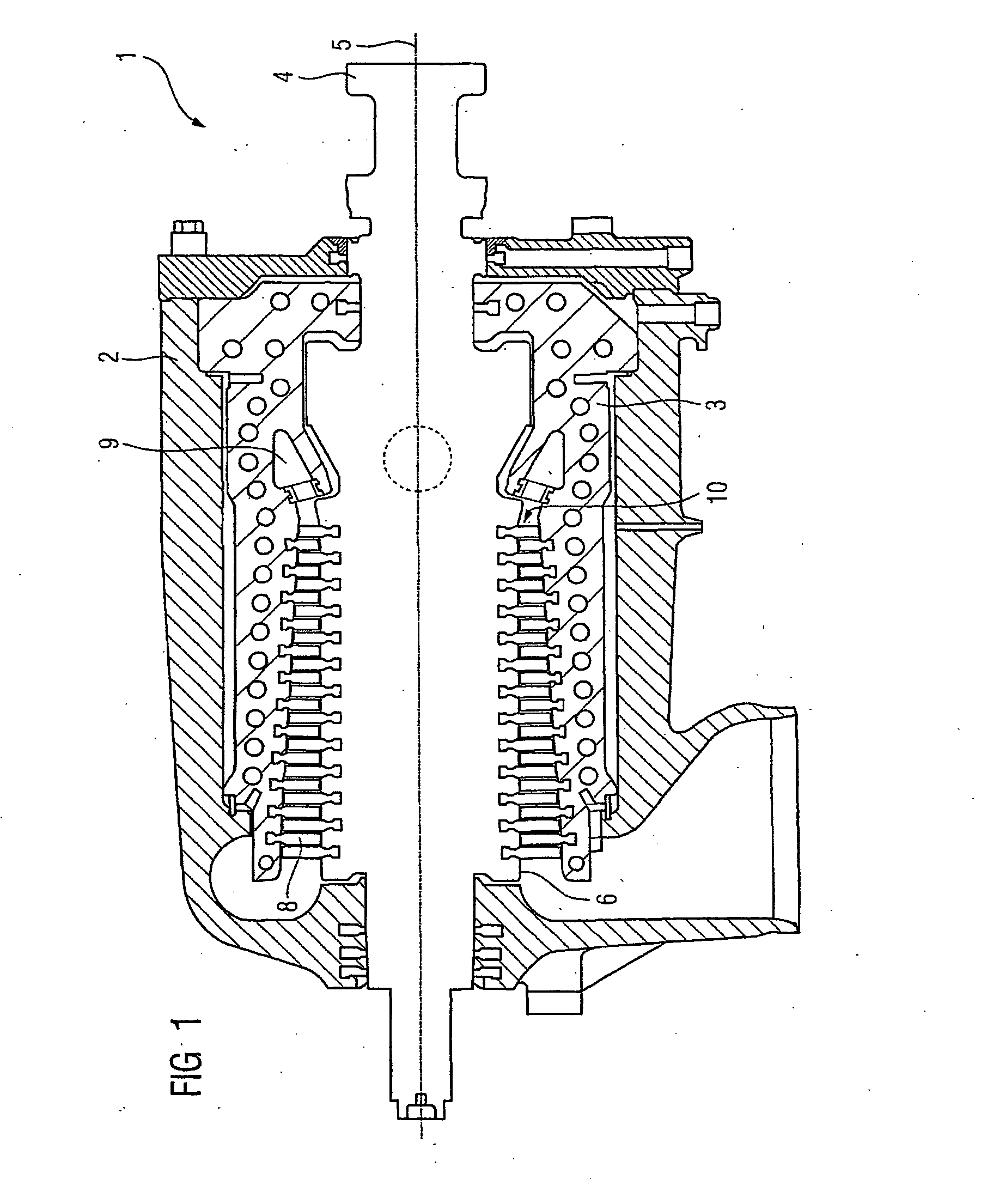
[0048]FIG. 1 shows a section through a steam turbine 1. The steam turbine 1 has an outer casing 2 and an inner casing 3. A shaft 4 is supported rotatably about an axis of rotation 5. On the shaft surface 6, turbine blades 7 are arranged in the circumferential direction. In the inner casing 3, turbine guide blades 8 are arranged. In operation, steam flows into an admission area 9 and expands when passing through a flow duct 10. During this process, a rotation is imparted to the shaft 4. As a result, a rotor, not shown in greater detail, of a generator can be placed into rotation.

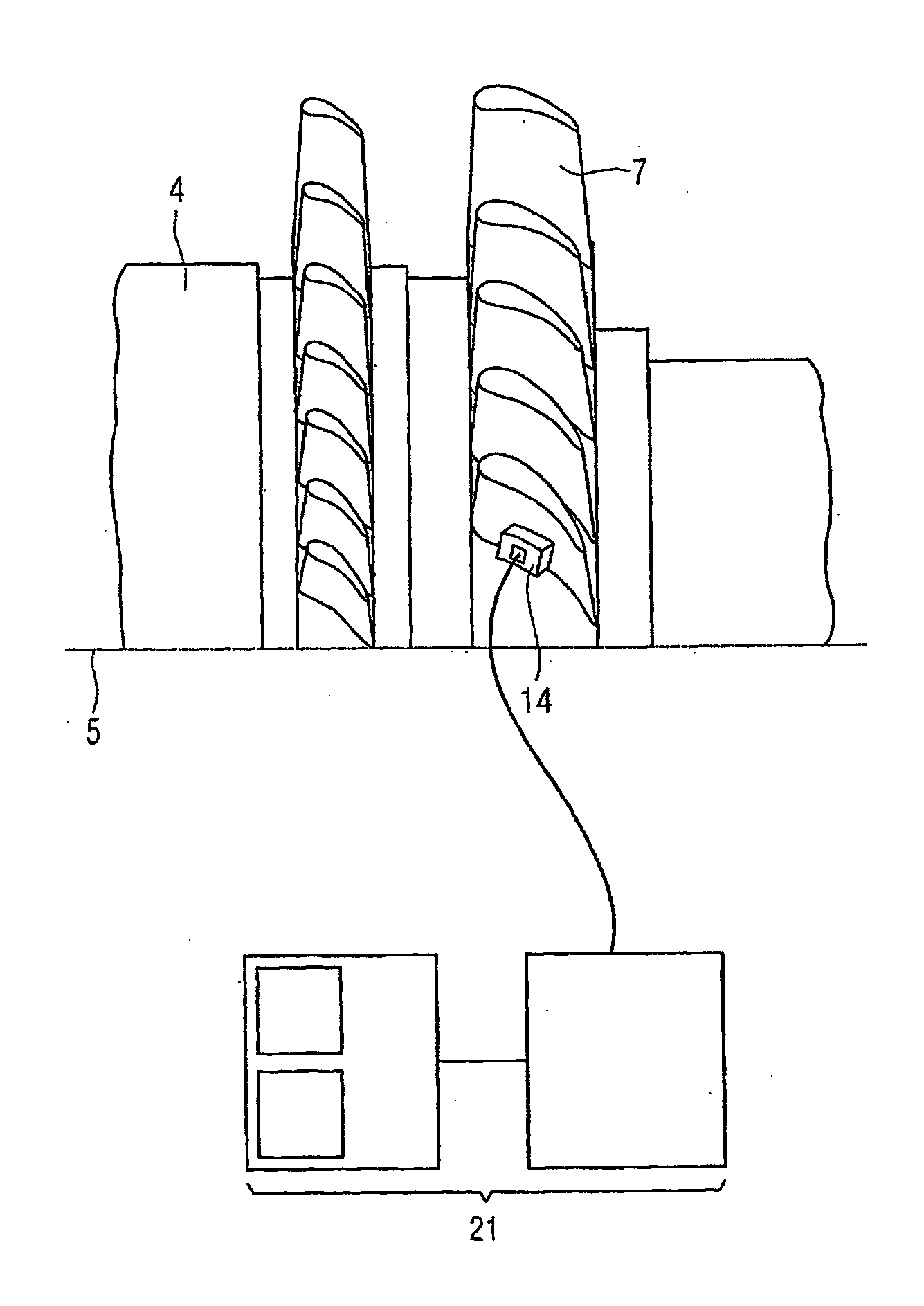
[0049]In inspection cases or in cases of damage, the outer casing 2 of the steam turbine 1 is opened, as a rule, to provide access to the individual turbine blades 7 on the shaft 4.

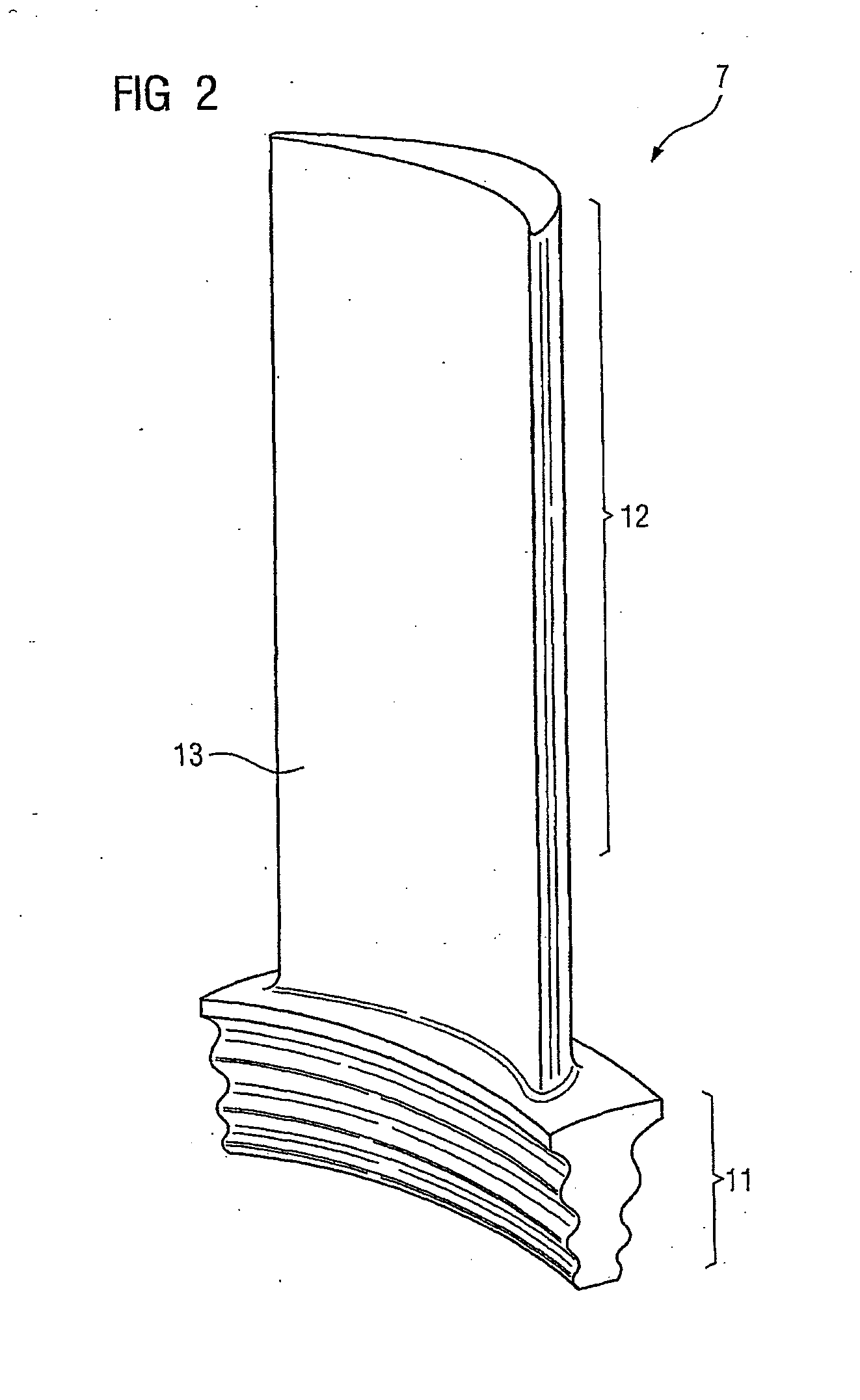
[0050]FIG. 2 shows a perspective view of a turbine blade 7. The turbine blade 7 has a turbine blade root 11. The turbine blade root 11 shown in FIG. 2 is constructed as so-called Christmas tree root. When the steam turbine 1 is ope...


PUM


Abstract

The invention relates to a method and a measuring and evaluation device for determining defects in a turbine blade and to a fixing device for fixing a probe to a turbine blade surface.

Description

CROSS REFERENCE TO RELATED APPLICATIONS[0001]This application is the US National Stage of International Application No. PCT / EP2005 / 052155, filed May 12, 2005 and claims the benefit thereof. The International Application claims the benefits of European Patent application No. 04012922.3 filed Jun. 1, 2004. All of the applications are incorporated by reference herein in their entirety.FIELD OF INVENTION[0002]The invention relates to a method and a measuring and evaluation device for determining defects in a turbine blade and to a fixing device for fixing a probe to a turbine blade surface.BACKGROUND OF THE INVENTION[0003]It is generally known that defects, e.g. in the form of cracks, have a negative effect on the strength of a component and thus also the reliability of the component. Under certain conditions, such cracks in the surface of components may grow. This applies, in particular, in the case of components such as, e.g. shafts, turbine blades or, in particular, turbine blade roo...

Claims


Application Information

Patent Timeline
IPC IPC(8): G01N29/24G01N29/11G01N29/22G01N29/28G01N29/46
CPCG01N29/11G01N29/223G01N29/28G01N29/46G01N2291/02854G01N2291/044G01N2291/106G01N2291/2693G01N29/22
Inventor CLOSSEN-VON LANKEN SCHULZ, MICHAELOPHEYS, MICHAEL
Owner SIEMENS ENERGY GLOBAL GMBH & CO KG
Why Eureka
Try Eureka