Dual panel system for controlling the passage of light through architectural structures

a technology of architectural structures and panels, applied in the field of transparent/translucent panel systems, can solve the problems of limited usefulness of prior approaches to controlling the amount of light passing through architectural structures, difficult or expensive construction and service, and limited knowledge of controlling the amount of light entering through glazing systems, etc., to achieve the effect of maximizing the effectiveness of the system, avoiding the loss of light, and being easy to access

Inactive Publication Date: 2008-10-16
CPI DAYLIGHTING
View PDF40 Cites 16 Cited by
  • Summary
  • Abstract
  • Description
  • Claims
  • Application Information

AI Technical Summary

Benefits of technology

[0010]It is one objective of this invention to provide a transparent / translucent panel unit in which the transmission of light across the system can be adjusted from almost full transparency or translucency to near total opacity. This is accomplished with two generally parallel spaced flat panels or sheets and a series of elongated, transparent / translucent light-controlling members disposed between the panels and mounted for rotation about their longitudinal axes. The spacing between the flat panels can be adjusted to accommodate different sizes of light-controlling members, from as little as 1 inch to 6 inches or more. Also, panel units of a highly desirable thickness or depth of about 2.75 to 4 inches or more can be produced to achieve outstanding insulation, soundproofing and structural characteristics. This makes the panels ideal for use in applications calling for high insulation values, substantial soundproofing and long span construction.
[0011]Once installed, the light-controlling members as well as other components housed between the panels can be readily accessed by removing one of the two parallel panels, leaving the second panel in place to protect areas enclosed by the panel system from exposure to the outside environment. Additionally, in one preferred embodiment of the invention, the light-controlling members may be positioned in abutting relationship to maximize the effectiveness of the system in blocking incoming light when the panel system is in the fully closed position.
[0012]Rotation of the light-controlling members may be by the application of rotary motion at one end (or less preferably at both ends) of each light-controlling member. The rotary motion may be applied to a plurality of the light-controlling members directly, as described, for example, in the '255 patent, or it may be applied indirectly. Thus, in one particularly important aspect of the invention, circular engagement surfaces are provided on adjacent light-controlling members. This enables the plurality of light-controlling members within a panel unit to be rotated by imparting rotary motion either manually or with a motorized drive to at least one of the light-controlling members which transmits the rotary motion indirectly across the contacting engagement surfaces of adjacent light-controlling members to rotate the light-blocking surfaces and vary the level of light passing through the panel unit. Also, the use of two spaced-apart panels (rather than a unitary panel as in the '255 patent) makes it possible to house some or substantially all of the drive mechanism between the panels and thus within the panel unit, out of the way of other structural components.
[0013]This system can maintain a perfect balance between light transmission and thermal performance, fostering a daylighted, comforting, livable and productive environment all year long. It also conserves energy on peak demand. The system may be fully automatic, with built-in intelligent light controllers and an embedded program that senses the daylight outside and manages the level of light and solar heat gain inside based on the level of sunlight outside. This will enable users to control natural daylight and comfort levels in any space all day long, and all year long, simply by setting desired light levels.

Problems solved by technology

The known approaches to controlling the amount of light admitted through glazing systems, however, are limited and are generally difficult or expensive to construct and service.
Prior approaches to controlling the level of light passing through architectural structures have been of only limited usefulness.
Furthermore, louver blinds are difficult and expensive to assemble, apply, operate, maintain and replace, and cannot be readily adapted for use in non-vertical applications or in applications in which it is either desirable or necessary to control the flexible members from only one end.
Also, if a tubular member fails, the entire panel must be removed and replaced.
This may be prohibitively complex and expensive in certain applications.
Where the panels are part of a protected enclosure, removal of an entire panel will expose the interior of the enclosure to the exterior environment which can be problematic.
Additionally, in the design of the '255 patent the diameter of the radiation blocking members is constrained by the size of the cells—where circumstances make larger or smaller radiation-blocking members desirable or necessary due to economic or other reasons, the system of the '255 patent cannot accommodate them.
This is a very complex and expensive design which could be made substantially simpler and less expensive if the same result could be achieved with fewer larger diameter radiation-blocking members or with simpler drive mechanisms that preferably could be substantially contained within the area defined by the panel.
Furthermore, the unitary cellular panel structure of the '255 patent resists bending, making it difficult to use the system in architectural applications where tight radius bends are required.
Additionally, the cellular-panel structure has insulation, soundproofing and structural limitations arising from its maximum 30 mm thickness or depth that make its use less than ideal in applications calling for high insulation values, substantial soundproofing and long span construction.
Finally, the unitary cellular panel structure of the '255 patent does not permit the use of different combinations of interior and exterior panel colors and finishes as required or desirable in many architectural applications.

Method used


Image

  • Dual panel system for controlling the passage of light through architectural structures
  • Dual panel system for controlling the passage of light through architectural structures
  • Dual panel system for controlling the passage of light through architectural structures

Examples


Embodiment Construction

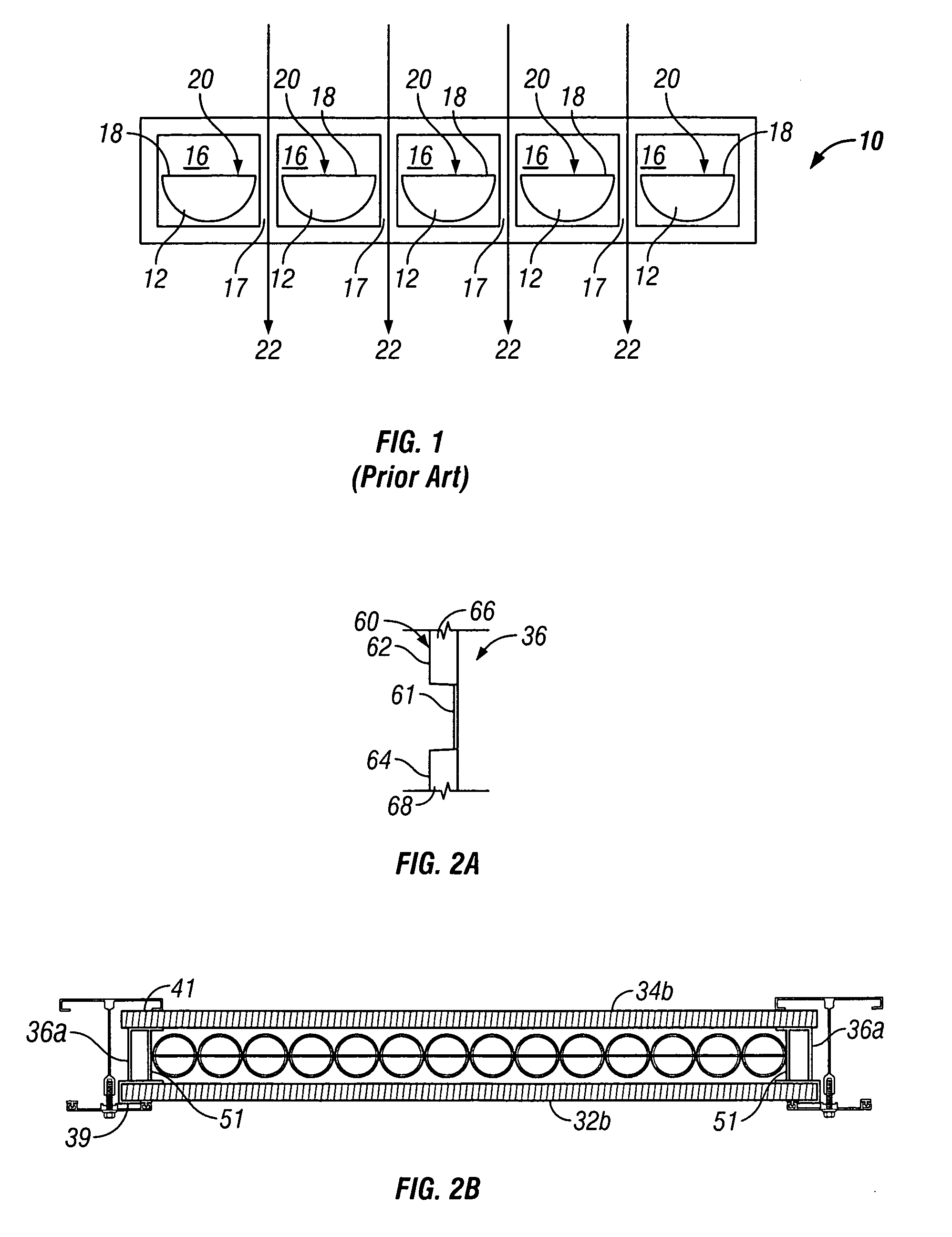
[0037]Turning first to FIG. 1, an elevational view of a transparent or translucent panel 10 in accordance with the teaching of prior U.S. Pat. No. 6,499,255 is shown. Panel 10 includes a series of half-cylinder louvers 12 rotatably mounted in a series of adjacent, segregated cells 16 separated by walls 17. Louvers 12 each have an opaque top surface 18. Thus, in the illustrated embodiment where the louvers are in the fully closed position, light rays 20 strike opaque surfaces 18, which block light transmission through the louvers. Unfortunately, the transparent or translucent material in the walls 17 between adjacent cells remains unblocked, which means that light rays 22 will penetrate the panel through these walls. Thus, even with all of the louvers in the fully closed position, the panels of the '255 patent admit light: in one commercial embodiment of this invention, the panels have been found to admit a minimum of about 6% light transmission. Also, the panel of the '255 consists ...


PUM


Abstract

The invention comprises a transparent / translucent panel system including two spaced flat panels and a series of elongated, abutting, rotatably mounted transparent / translucent light-controlling members disposed between the panels in which the light-controlling members are at least partially tubular or have annular members along their length to facilitate rotation of the light-controlling members and include a light-blocking surface whereby differently sized light-controlling members may be used and the light-controlling members, when rotated by a simple drive mechanism, can vary the light passing through the panel system from clear to opaque and can effectively block light between adjacent light-controlling members.

Description

[0001]This application is a continuation of U.S. patent application Ser. No. 10 / 600,261, filed Jun. 20, 2003. The entire disclosure of the foregoing patent application is hereby incorporated by reference.FIELD OF THE INVENTION[0002]This invention relates to architectural structures designed to pass light and, more particularly, to transparent / translucent panel systems for controlling the level of light admitted through sloped glazing, skylights, roofs, walls, and other architectural structures designed to pass light.BACKGROUND OF THE INVENTION[0003]Various types of transparent and translucent glazing systems are available for the construction of sloped glazing, skylights, roofs, walls, and other architectural structures designed to pass light for daylighting interiors and other purposes. When using such glazing systems, it is often desirable to optimize the system's shading coefficient by reducing solar heat gain on hot summer days and during peak sunlight hours year round, while pr...

Claims


Application Information

Patent Timeline
Patent Type & Authority Applications(United States)
IPC IPC(8): E04D13/18E04D13/03A01G9/22A01G9/24E04D3/06E04F10/08E06B7/096E06B9/24H01L31/00H01L31/042
CPCA01G9/22A01G9/243E04D3/06E04D13/033E04F10/08E06B9/24F24J2/407F24J2/5262Y02B10/12Y02B10/20Y02B80/50E04F10/10F24S50/80F24S25/67Y02A30/24Y02A40/25Y02B10/10Y02B80/00Y02P60/12Y02P60/14
Inventor KONSTANTIN, MOSHE
Owner CPI DAYLIGHTING
Why Eureka
Try Eureka