
Internally Overlapped Conditioners

Inactive Publication Date: 2008-10-09
X2Y ATTENUATORS L L C
View PDF99 Cites 1 Cited by
  • Summary
  • Abstract
  • Description
  • Claims
  • Application Information

AI Technical Summary

Benefits of technology

[0012]This application discloses novel energy conditioner structures and novel combinations of the connections of the energy conditioners on other structures, such as PC board structures, and novel circuit arrangements of the energy conditioners with structures, such as PC boards, described herein, generally provide improved decoupling, per conditioner, and require less conditione

Problems solved by technology

Electrical circuits using low frequency electrical power generate noise that is coupled through the power distribution system.
That noise is generally detrimental.

Method used


Image

  • Internally Overlapped Conditioners
  • Internally Overlapped Conditioners
  • Internally Overlapped Conditioners

Examples


Embodiment Construction

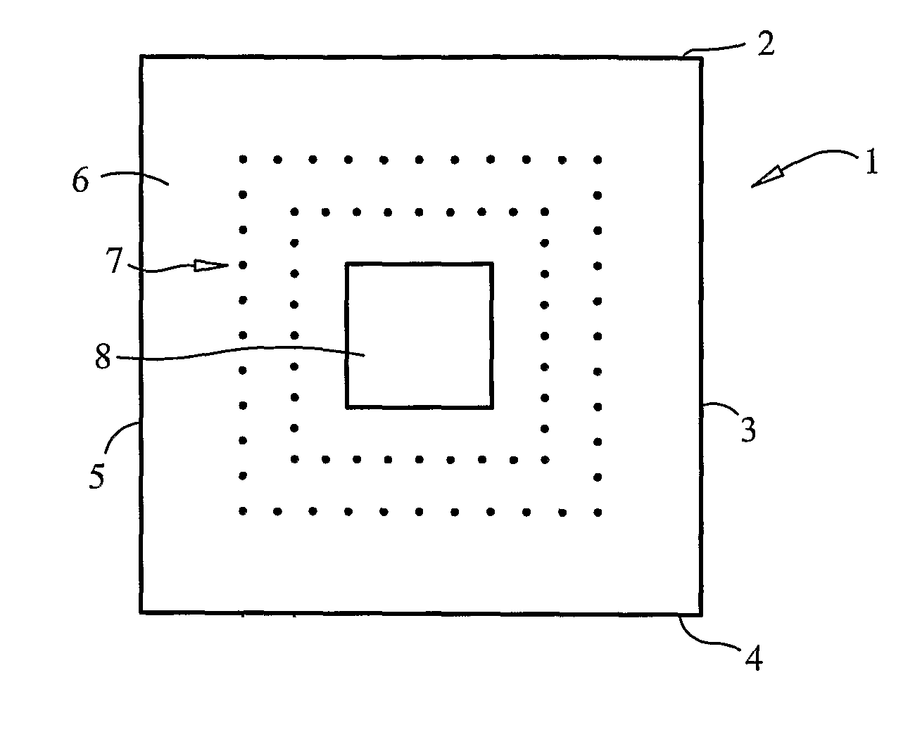
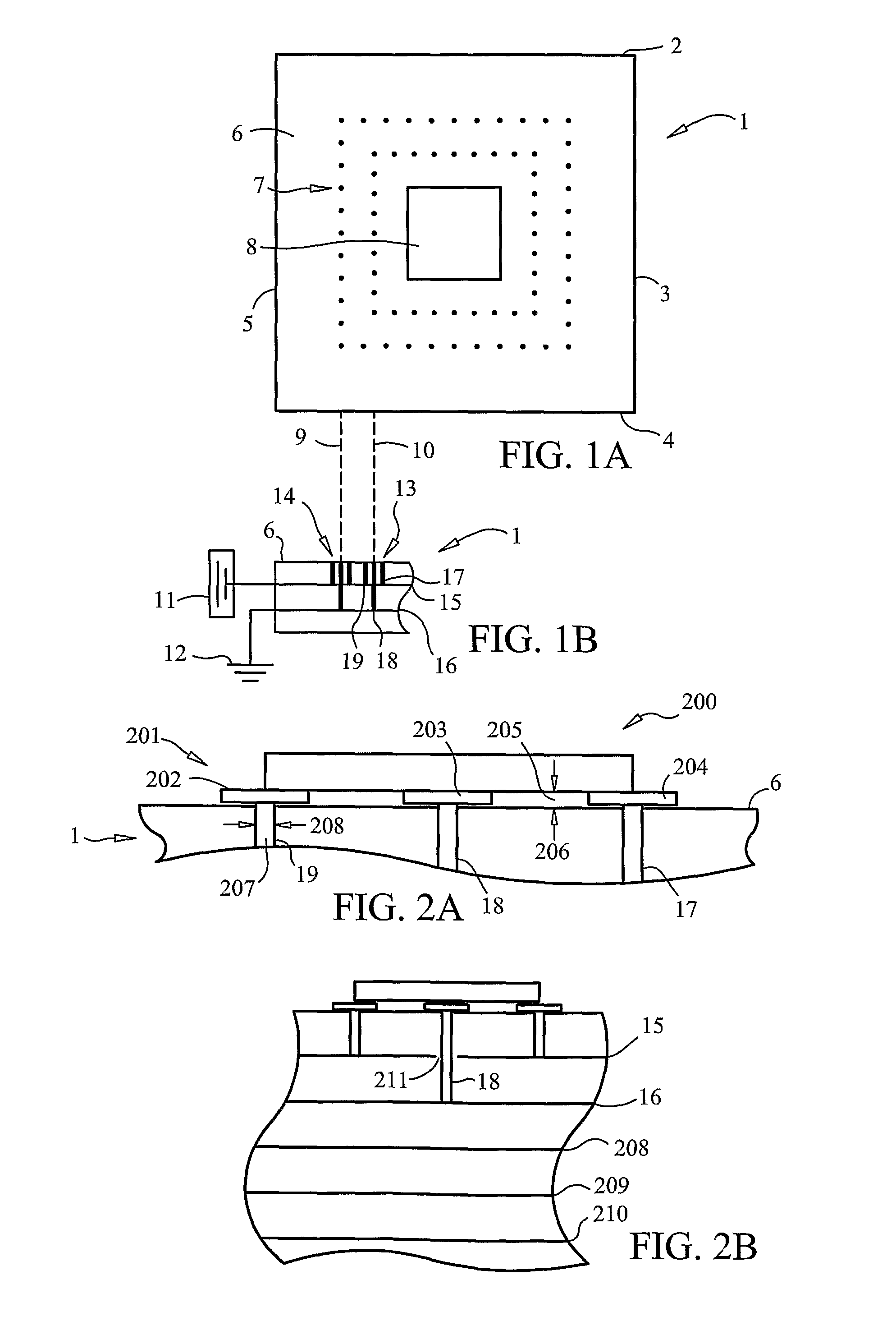
[0083]FIG. 1A shows PC board 1 having sides 2, 3, 4, and 5, top surface 6, array 7 of structure for mounting discrete capacitors, and region 8 for mounting an IC. Each side of array 7 defines plural rows, such as rows 9 and 10. Each element or array 7 represents mounting structure for mounting a discrete capacitor. Conventional PC boards often have an array including at least two rows of structure for mounting capacitors. Each row may have several to tens of array elements for mounting capacitors. The board is designed so that capacitors mounted to the elements of array 7 sufficiently decouple the power to the IC from active circuitry so that the IC and any other coupled circuit elements functions as intended.

[0084]Conventional capacitors are two terminal discrete devices.

[0085]FIG. 1B shows a portion of board 1, a source of electrical power 11, a ground 12, mounting structure 13 corresponding to one element of array 7, mounting structure 14 corresponding to another element of array...


PUM

PropertyMeasurementUnit
Timeaaaaaaaaaa
Structureaaaaaaaaaa
Electrical conductoraaaaaaaaaa

Abstract

The application discloses novel internal structures of energy conditioners, assemblies of external structures of energy conditioners and mounting structure, and novel circuits including energy conditioners having A, B, and G master electrodes.

Description

CROSS REFERENCE TO RELATED APPLICATIONS[0001]This application claims priority to the U.S. provisional applications:[0002]60 / 656,910, filed Mar. 1, 2005 (attorney docket number X2YA0051P-US);[0003]60 / 661,002, filed Mar. 14, 2005 (attorney docket number X2YA0052P-US);[0004]60 / 668,992, filed Apr. 7, 2005 (attorney docket number X2YA0055P-US);[0005]60 / 671,107, filed Apr. 14, 2005 (attorney docket number X2YA0053P-US);[0006]60 / 671,532, filed Apr. 15, 2005 (attorney docket number X2YA0049P-US);[0007]60 / 674,284, filed Apr. 25, 2005 (attorney docket number X2YA0054P-US); and[0008]60 / 751,273, filed Dec. 19, 2005 (attorney docket number X2YA0056P-US).[0009]The disclosures of the foregoing applications are all incorporated by reference herein.FIELD OF THE INVENTION[0010]This invention relates to energy conditioning.BACKGROUND OF THE INVENTION[0011]Electrical circuits using low frequency electrical power generate noise that is coupled through the power distribution system. That noise is general...

Claims


Application Information

Patent Timeline
IPC IPC(8): H01R12/24
CPCH01G4/005H01G4/232H01G4/30H05K1/0231H05K1/113Y10T29/49002H05K2201/0979H05K2201/10636H01G4/35Y10T29/43H05K1/114Y02P70/50H01G4/40H02H9/06H01L27/10G11C5/14
Inventor ANTHONY, WILLIAM M.ANTHONY, DAVIDANTHONY, ANTHONY
Owner X2Y ATTENUATORS L L C
Learn More