
Selective Hydrogenation Process Using Layered Catalyst Composition and Preparation of Said Catalyst

a technology of layered catalysts and hydrogenation processes, applied in the field of selective hydrogenation of hydrocarbons, can solve the problems of not producing the desired detergent precursors, and achieve the effects of reducing the capital cost of the process, high space velocities, and high space velocities

Inactive Publication Date: 2008-10-09
UOP LLC
View PDF25 Cites 16 Cited by
  • Summary
  • Abstract
  • Description
  • Claims
  • Application Information

AI Technical Summary

Benefits of technology

[0020]The selective hydrogenation process disclosed herein is believed to be capable of operating at relatively higher space velocities for a given reaction temperature and equilibrium conversion of diunsaturates than prior processes. Without limiting this invention to any particular theory, it is believed the layered catalyst used in the selective hydrogenation process disclosed herein has less restrictions to diffusion of reactants and products in comparison to previous catalysts. Consequently, it is expected that the temperature required to attain a specified equilibrium conversion would be lower and also that at a given conversion higher space velocities could be attained without excessive reactor temperature. Therefore, less catalyst and a smaller reactor would be needed, which would result in reduction in the capital cost of the process.

Problems solved by technology

These diolefins do not alkylate benzene in the same way as the monoolefins and therefore do not produce the desired detergent precursors.

Method used


Image

  • Selective Hydrogenation Process Using Layered Catalyst Composition and Preparation of Said Catalyst
  • Selective Hydrogenation Process Using Layered Catalyst Composition and Preparation of Said Catalyst

Examples


example 1

[0057]One catalyst of the invention was prepared by impregnating a cordierite sphere having a 100 micron outer layer of alumina with a liquid solution of palladium nitrate, copper nitrate and potassium nitrate. The resulting solution was evaporated to dryness and the sample was calcined at 450° C. (842° F.). The sample was then reduced at 200° C. (392° F.) with hydrogen. Standard impregnation conditions and techniques were employed and the following metal loadings based on the weight of the catalyst were achieved: 0.02 wt-% Pd, 0.038 wt-% Cu and 0.33 wt-% K.

example 2

[0058]A second catalyst of the invention was prepared by impregnating a cordierite sphere having a 100 micron outer layer of alumina with a liquid solution of palladium nitrate, silver nitrate and potassium nitrate. The resulting solution was evaporated to dryness and the sample was calcined at 450° C. (842° F.). The sample was then reduced at 200° C. (392° F.) with hydrogen. Standard impregnation conditions and techniques were employed and the following metal loadings based on the weight of the catalyst were achieved: 0.02 wt-% Pd, 0.065 wt-% Ag, and 0.33 wt-% K.

[0059]The diolefin conversion and selectivity of the catalysts prepared in Examples 1 and 2 were studied using as feed the product of a commercial catalytic dehydrogenation unit. Based on analyses of other similar feeds from the same source, the feed used in Examples 1 and 2 is believed to have the composition shown in Table 1. A volume of the catalyst to be tested was loaded in a reactor, and the feed flow was started unde...

example 3

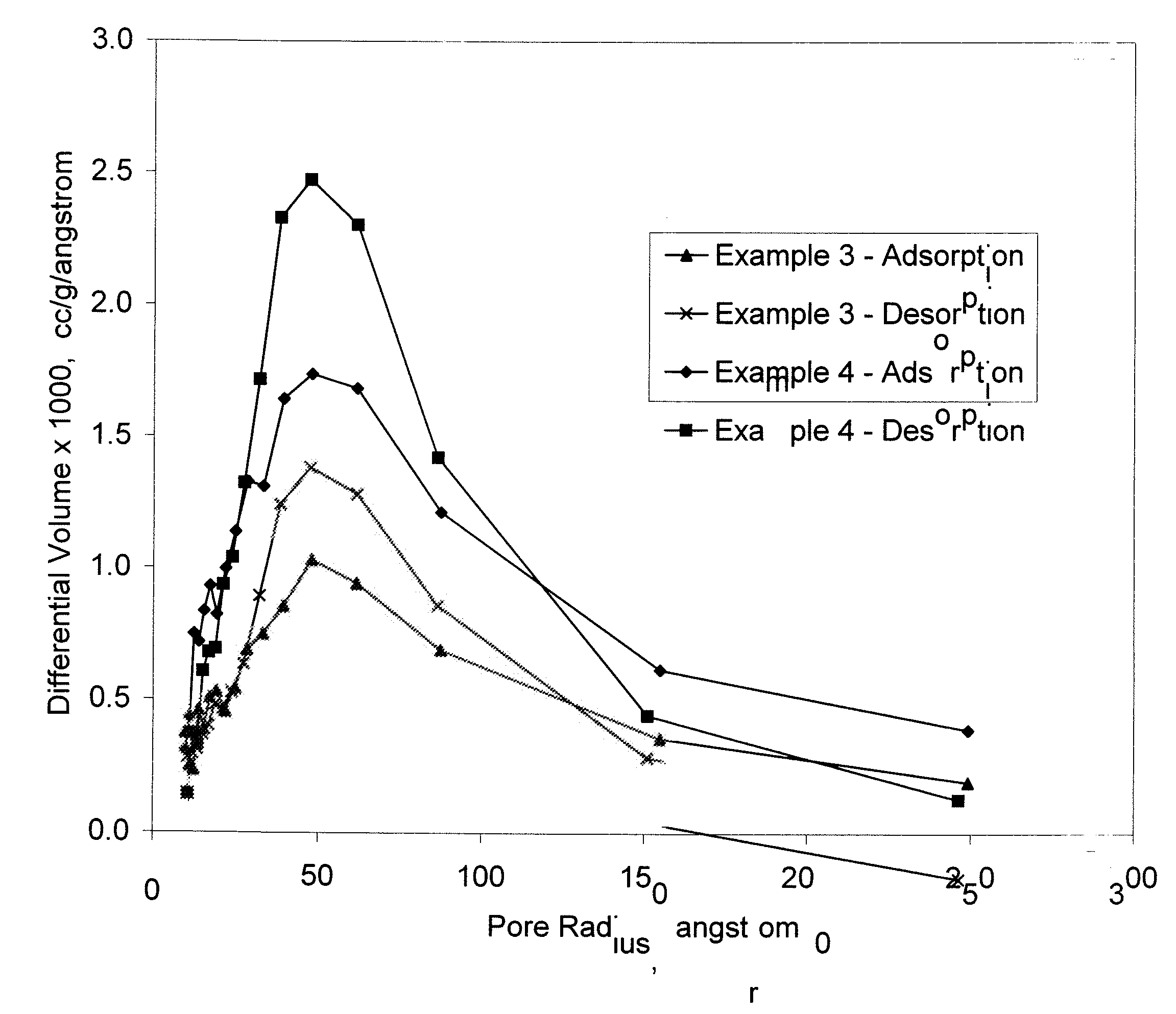
[0064]The catalyst of Example 1 was studied using desorption and adsorption techniques to determine the pore size distribution, the average pore radius, the surface area and the total pore volume of the catalyst. The results of the studies are shown in Table 3.


PUM

PropertyMeasurementUnit
temperatureaaaaaaaaaa
thicknessaaaaaaaaaa
temperaturesaaaaaaaaaa

Abstract

A selective hydrogenation process and a layered catalyst composition for use in the selective hydrogenation process are disclosed. The process is useful for the selective hydrogenation of diolefins having from about 8 to about 19 carbon atoms per molecule to monoolefins.

Description

CROSS REFERENCE TO RELATED APPLICATION[0001]This application is a Division of prior copending application Ser. No. 11 / 312,999, filed Dec. 20, 2005, now allowed, which is incorporated herein by reference in its entirety.FIELD OF THE INVENTION[0002]The invention relates to the selective hydrogenation of hydrocarbons. More specifically, the invention relates to the use and preparation of a catalyst to selectively hydrogenate C8-C19 diolefins to C8-C19 monoolefins.BACKGROUND OF THE INVENTION[0003]The present invention relates to the use and preparation of a layered catalyst to selectively hydrogenate C8-C19 diolefins to C8-C19 monoolefins. C8-C19 monoolefins are valuable intermediates in the manufacture of alkylbenzene detergent precursors. The layered catalyst composition comprises an IUPAC Group 10 metal and an IUPAC Group 11 metal on a layered composition support. The support comprises an inner core of a refractory inorganic component, such as cordierite and an outer layer of a refra...

Claims


Application Information

Patent Timeline
Patent Type & Authority Applications(United States)
IPC IPC(8): B05D3/10
CPCB01J23/58B01J23/66B01J23/8946B01J35/008B01J35/08B01J35/1014B01J35/1038B01J35/1061B01J35/108B01J37/0221B01J37/0242B01J37/16B01J37/18C10G2400/22B01J35/397B01J35/51B01J35/613B01J35/633B01J35/647B01J35/66
Inventor GAJDA, GREGORY J.
Owner UOP LLC
Learn More