
High intensity laser power beaming receiver for space and terrestrial applications

a laser power beaming and receiver technology, applied in the direction of lighter-than-air aircraft, transportation and packaging, efficient propulsion technologies, etc., can solve the problems of limiting the capacity of the power plant, increasing the design cost, and affecting the beaming speed of the laser beaming device, so as to facilitate the laser power beaming and dissipate heat

Inactive Publication Date: 2008-10-09
CLEVELAND STATE UNIVERSITY
View PDF7 Cites 24 Cited by
  • Summary
  • Abstract
  • Description
  • Claims
  • Application Information

AI Technical Summary

Benefits of technology

[0006]The present invention contemplates new and improved systems and methods that resolve the above-referenced difficulties and others.
[0007]Systems and methods for receiving a high-intensity directed laser at a vehicle and converting laser light energy into electrical energy to power the vehicle are provided.
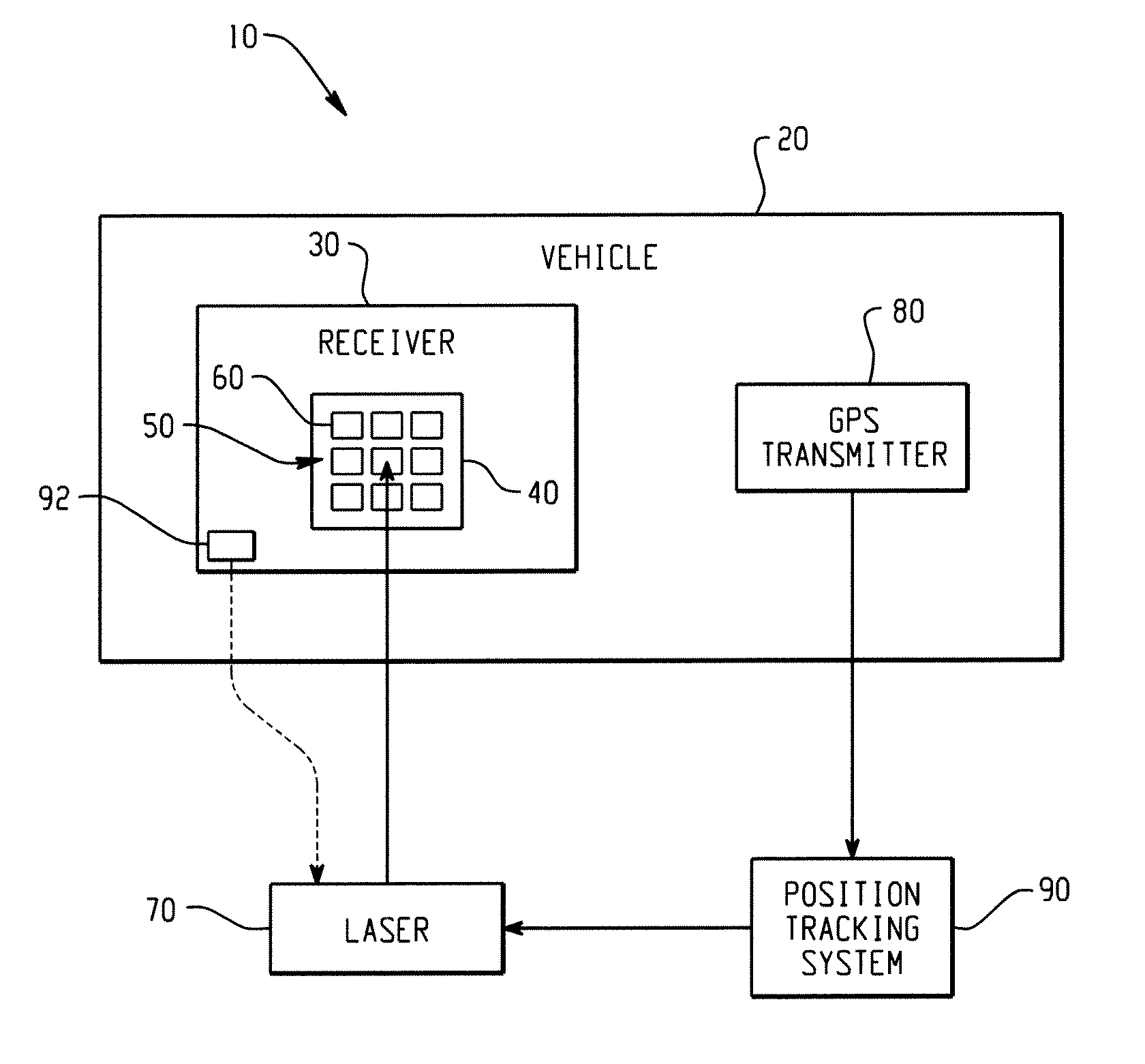
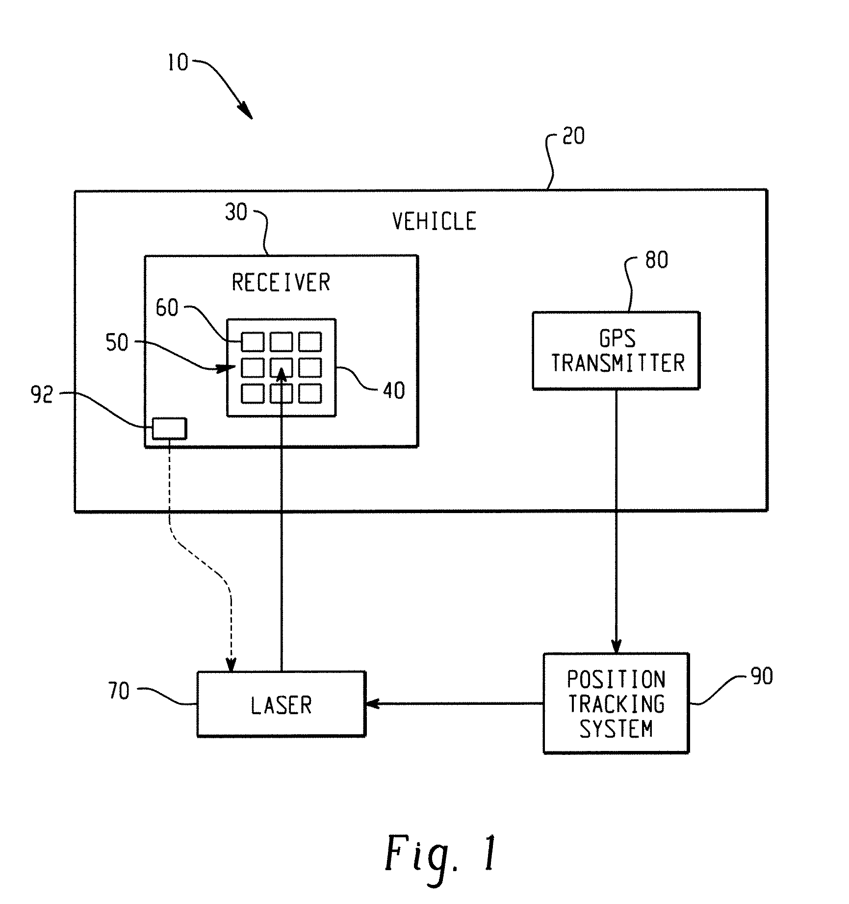
[0008]In one aspect, a system that facilitates laser power beaming comprises a receiver mounted to a vehicle and electrically coupled thereto, an array of vertical multi-junction (VMJ) photocells, positioned on the receiver to receive a laser beam, and a global positioning system onboard the vehicle, which transmits location information. The system further comprises a remote position tracking system that receives the location information from the global positioning system, and a high-intensity laser that receives targeting information from the position tracking system, targets the receiver on the vehicle, and provides a laser beam pulse thereto. The VMJ photocells convert at least a portion of the received laser beam energy to electrical energy for use by the vehicle.
[0009]In another aspect, a method of mid-air refueling of a vehicle using a near-infrared laser comprises receiving location coordinate information from the vehicle, targeting a receiver on the vehicle with a near-infrared laser source, directing a laser beam form the laser source to a laser-receiving array on the receiver, and receiving the laser beam at one or more vertical multi-junction (VMJ) photocells in the laser-receiving array. The method further comprises converting received laser energy into electrical energy, storing the electrical energy in the VMJ photocells for use by the vehicle, and dissipating heat caused by unconverted laser energy into the ambient atmosphere.

Problems solved by technology

By way of background, a fundamental problem with modern day combat and surveillance using manned and / or unmanned aircrafts is the onboard fuel capacity.
This drives up design costs dramatically and limits the power plant capacity, thereby seriously reducing maneuverability and limiting mission life, especially in the case of unmanned aerial vehicles (UAVs) such as the Global Hawk and the Predator.
Conventional systems do not permit such aircraft to receive fuel as frequently as desired, while in mid-air, from far away platforms to remove the fuel and power limitations currently encountered by UAVs.

Method used


Image

  • High intensity laser power beaming receiver for space and terrestrial applications
  • High intensity laser power beaming receiver for space and terrestrial applications
  • High intensity laser power beaming receiver for space and terrestrial applications

Examples


Embodiment Construction

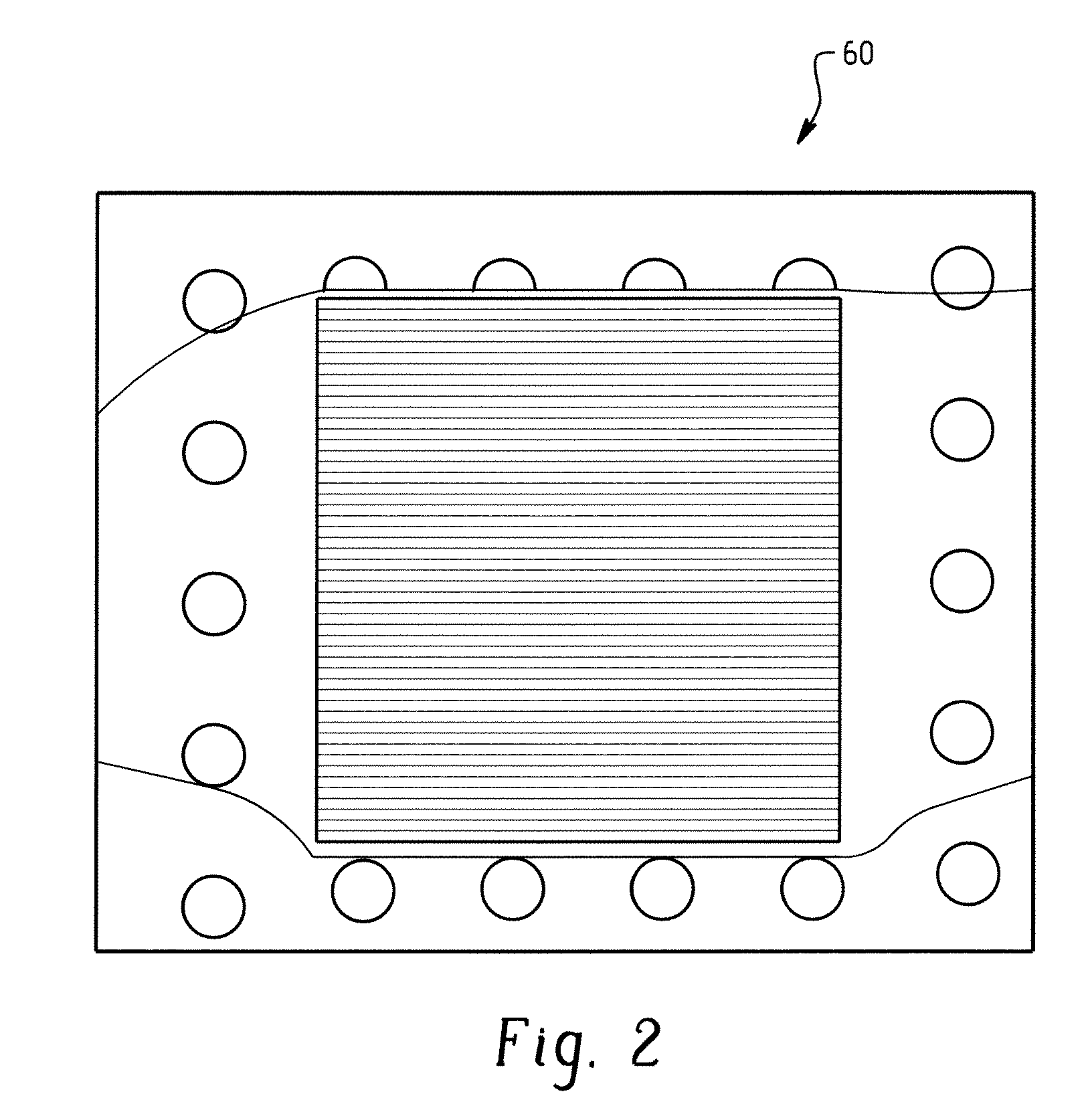
[0022]Referring now to the drawings, which are presented for purposes of illustrating various embodiments only and not for purposes of limiting the claimed subject matter, various aspects of the innovation are depicted that relate to a high-intensity laser power receiving system for operations in the atmosphere and / or in space. Additionally, “exemplary,” as used herein, is to be interpreted to mean “an example of.”FIG. 1 illustrates a system 10 that employs high-intensity laser power beaming (HILPB) technology in conjunction with highly energetic photovoltaic cells to transmit large quantities of power wirelessly over large distances. The system 10 includes a vehicle 20, such as an unmanned aerial vehicle (UAV) and miniature UAV (MUAV), with a receiver 30 that optionally includes an aperture 40 for receiving high-intensity laser light. The laser light passes through the aperture and is incident upon a photovoltaic array 50 comprising one or more high-energy photocells 60. In another...


PUM


Abstract

Systems and methods are described that facilitate refueling a vehicle with electrical energy by targeting receiver thereon and pointing a high-intensity laser source at the receiver. Vertical multi-junction (VMJ) photocells receive the laser energy and convert the laser energy into electrical energy. The laser source can operate at a range of output power levels depending on the vehicle's energy needs. The laser source can be pulsed or continuous near-infrared laser source. A heat exchanger can be coupled to the receiver to dissipate laser energy not converted into electrical energy. If the vehicle has a propeller, the heat exchanger can be mounted to the vehicle in the propeller wash path.

Description

[0001]This application claims priority to U.S. Provisional Application Ser. No. 60 / 878,605, entitled HIGH-INTENSITY LASER POWER BEAMING SYSTEM FOR MILITARY AND CIVILIAN APPLICATION, filed on Jan. 4, 2007, the entirety of which is incorporated herein.[0002]The U.S. Government has a paid-up license in this invention and the right in limited circumstances to require the patent owner to license others on reasonable terms as provided for by the terms of Grant No. NCC 3-1081 awarded by NASA-GRC.BACKGROUND OF THE INVENTION[0003]This invention relates to a method and apparatus for receiving high-intensity laser light and converting it into electrical energy for refueling a vehicle or a space craft.[0004]While the invention is particularly directed to the art of refueling aerial vehicles, and will be thus described with specific reference thereto, it will be appreciated that the invention has usefulness in other fields and applications.[0005]By way of background, a fundamental problem with m...

Claims


Application Information

Patent Timeline
Patent Type & Authority Applications(United States)
IPC IPC(8): H01S3/00B64D39/00B64D33/00
CPCB64C2201/042B64D27/24B64D39/00H02J17/00Y02T50/62H02J50/30Y02T50/60H01L31/047Y02E10/50B64U50/19B64U50/31
Inventor NAYFEH, TAYSIR H.FAST, BRIAN R.RAIBLE, DANIELTOLLIS, NICKJALICS, ANDREWDINCA, DRAGOS
Owner CLEVELAND STATE UNIVERSITY
Learn More