Hypershelter

Active Publication Date: 2008-10-09
REGAN MICHAEL
View PDF9 Cites 5 Cited by
  • Summary
  • Abstract
  • Description
  • Claims
  • Application Information

AI Technical Summary

Benefits of technology

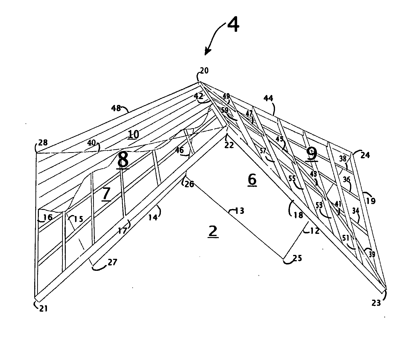
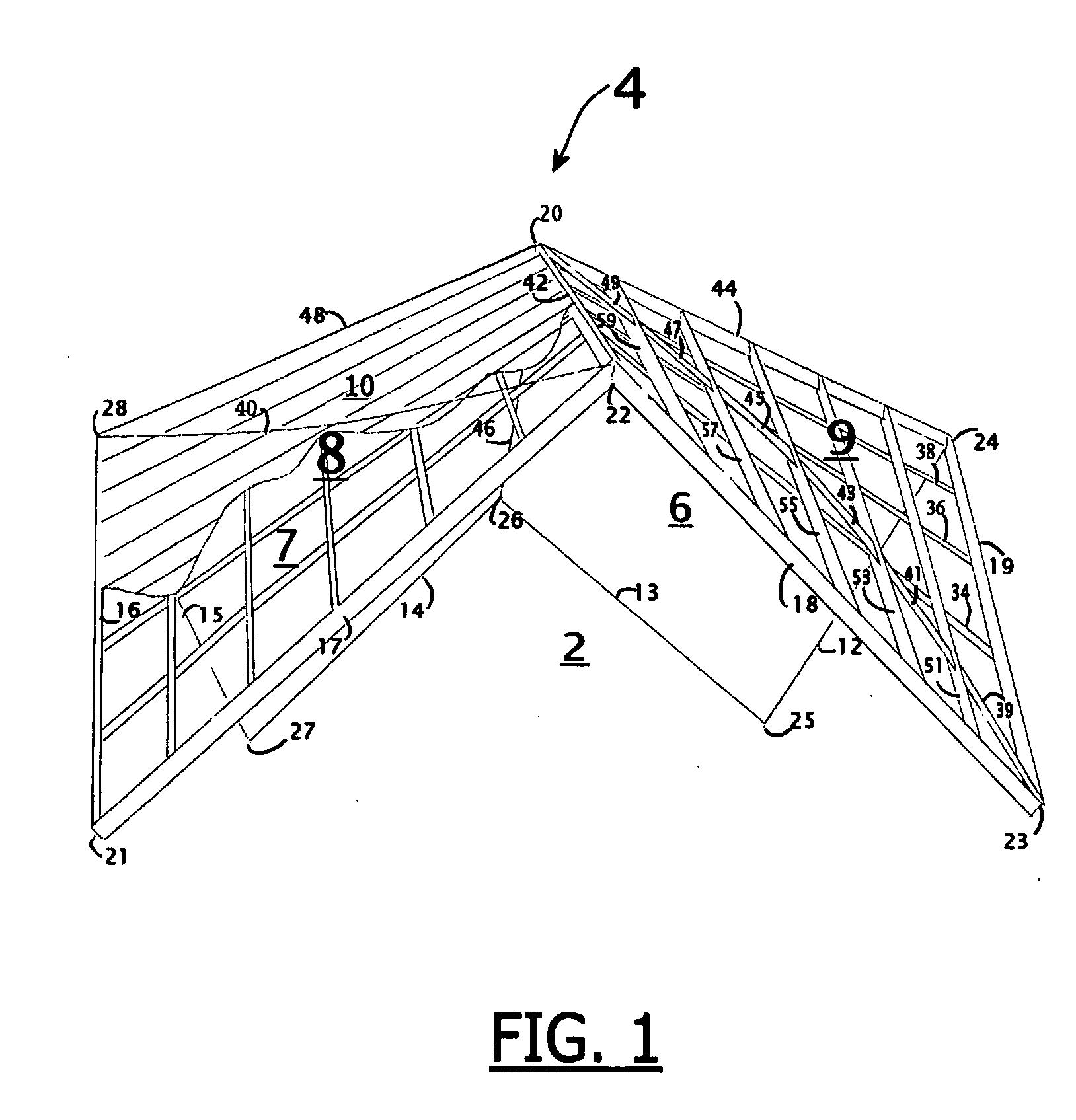
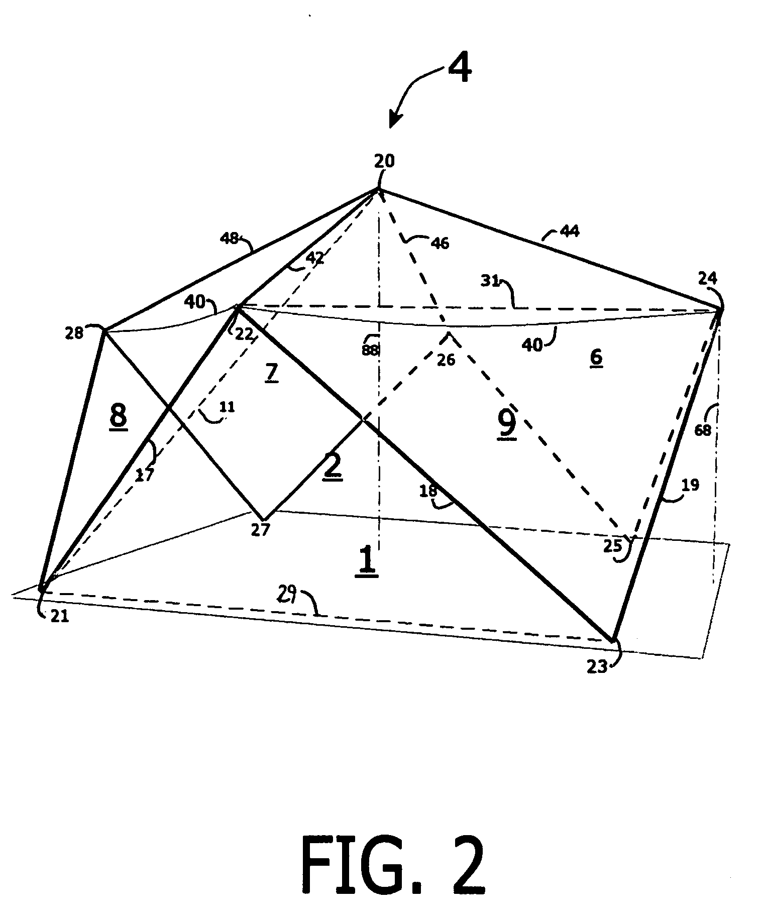
[0010]The curvature of each face is achieved by the succession of progressively oriented, near-parallel, straight framing members together with successively applied strips of covering materials. The covering materials are joined to the framing, and to each other, making the entire structure a continuous whole. To accommodate the gradual curvature only requires a slight twisting of each sheet of the covering materials as they are applied to the framing. The hyperbolic paraboloid curvature thus achieved allows the covering materials to play a role in supporting their own weight.
[0011]In medium to larger scales, a tension member (“tension restraining member”), attached at the peaks of the triangular openings, and running circumferentially around the structure stabilizes the framework during construction, and restrains the outward thrust imposed by weight such as a snow-load resting on the roof.
[0012]Each face has a compound curvature, arching inward vertically, and curving outward horizontally (a hyperbolic paraboloid) in the preferred embodiment. Within the framing, a series of optional radial braces connecting each pair of successive members from the base to the peak may be attached, following a locus of lines forming an arch, capable of carrying great loading forces to the ground. Additional such arches can be formed, each running substantially parallel to the primary ones. The tension restraining member also exerts an upward force on the framing in the hyperbolic paraboloid spans, which adds to the load-bearing capability. For some uses, semi-liquid materials such as cement, foam, or fiberglass with resin, which are designed to harden when cured, may be applied onto the hyperbolic paraboloid surfaces.

Problems solved by technology

(1) The traditional pup-tent, (a prism-shape, or, alternatively, a pyramid shape), had to be anchored to the ground, in part to make more usable interior space by pulling the sagging skin outward. This puts additional tension on the skin, and compression on the poles. It also takes up space on the exterior, making it difficult to walk around the tent without tripping on these tension lines. Other prism shapes, such as the “A-frame” buildings, also have problems, one of the biggest being their large surface areas, through which heat is lost.
(2) Another traditional solution has been to use a cubical configuration, in which the walls are vertical, and are made rigid by the application of sheathing materials or diagonals inserted into the framing. The roof is typically constructed by means of trussing, resulting in either a peaked or a flat roof. A big drawback is that this type of building requires more lumber per square foot of usable space than either a geodesic dome, or a “hypershelter”. A lot of material is used in the trusses, and the over-all building is thus top-heavy. A volume of the covered space is unusable, being inside the jungle of triangles in the attic. The instant invention contains a greater usable volume for a given surface area than any cubical structure, and is therefore more economical both in the expenditure of materials, and in the amount of labor required.
(3) A solution recently employed has been to use a dome shape with the outward forces being supplied by very long tent-poles, held under constant stress by being bent. This is very workable on small scales, and yields good strength-to-weight ratios as well as high volume-to-surface-area ratios because of the near-hemispherical shape. However, such stressed arches are not effective when rigidity is desired, and it is difficult to apply to larger structures for two reasons: (A): Assembling long, continuous, stressed framing members becomes more unwieldy as size increases, and (B): Strength-to-weight ratios decrease as overall size increases, because weight goes up on a function of the cube of the increase, whereas strength only increases on a squaring function. This makes it difficult to find the appropriate material of sufficient resiliency to support its own weight when used as a stressed arch.
(4) The use of panel constructions which can be assembled into building structures of various sizes, shapes, and types. Systems for attaching the panels to each other; and building structures of panel-type construction, are well known in the art. For example, see U.S. Pat. No. 3,945,160 to Grosser.
(5) Also known in the art is the assembling of panel constructions into geodesic dome structures. For example, see U.S. Pat. No. 4,160,345 to Nalick. The connectors for forming the structures by joining panel construction together is also well known in the art. For example see U.S. Pat. No. 6,173,547 to Lipson. When constructing a geodesic dome type structure such as in U.S. Pat. No. 2,682,235 to Fuller, or U.S. Pat. No. 6,295,785 to Herrman, a bottom edge is created that is typically raised over a substantially cylindrical portion into which doors and windows are fitted. As with these references and with U.S. Pat. No. 5,305,564 to Fahey, cells are typically arranged in circular rows. Each cell has edges, and as with triangles, they require special connectors and edge materials, which increase the cost of construction.
1) The triangles, though mass-producible in repeating patterns in a geodesic dome, create challenges in cutting covering materials, because these are commonly produced in rectangular forms, and require cutting to specifications which inevitably entail waste of unusable scraps.
2) The erection of the framework of a geodesic dome usually involves assembling the struts into successive courses of triangles, which, on large scales, requires the use of a crane and / or scaffolding. These initial courses are very unstable until the succeeding courses are assembled on them.
3) There are a large number of edges between triangles in a geodesic dome, and these constitute a very great length, simply because the triangle is the shape with the most perimeter to surface area. Although the planes join at obtuse angles so the ridges are less sharp, these edge lengths constitute a serious problem for the geodesic dome. The instant invention requires a minimum of such ridges, or edges. An N-way hypershelter has only N ridges.
4) Associated with the above is the difficulty of creating openings such as windows and doors, which must either be restricted within given triangles, or require the radical shape and re-engineering required in the creation of dormers or other protrusions. Openings such as skylights made in roof panels also engender the care and expense required in waterproofing.
5) Another drawback of the geodesic dome structures is that highly sophisticated crews and specialized connecting hardware must be employed for construction.
But, in those constructions, the builders have resorted to the use of expensive pre-formed panels to achieve the compound curvature required in a hyperbolic paraboloid shape, or other elaborate preforms, or have designed complex connectors.

Method used


Image

  • Hypershelter
  • Hypershelter
  • Hypershelter

Examples


Embodiment Construction

[0001]While several embodiments of the present invention have been shown and described, it will be apparent to those skilled in the art that many changes and modifications may be made without departing from the invention in its broader aspects.

FIELD OF INVENTION

[0002]The present invention relates generally to an improved structural configuration and method for assembling structures with hyperbolic paraboloid faces.

BACKGROUND OF THE INVENTION

[0003]There have long been efforts to construct buildings and tents that span a floor area without the need for intrusive interior supports. The typical approach is to assemble a framework of rigid linear materials, which is then covered with a surfacing material, or skin.

[0004]Stresses must be carried by a combination of tension and compression members, organized into a system that carries the distributed loads of the skin, and focuses them onto several support points on the ground. The total of all compression forces equals the total of all ten...


PUM


Abstract

The instant invention is a method for achieving a-planar framing configurations which enable the construction of hyperbolic paraboloid surfaces, a multiplicity of which join to create roof structures and enclosures.In particular, the shaping and erecting of connected a-planar quadrilateral frames to create under-framing which can be completed by a simple in-framing, and covered with sheeting material resulting in a new method of constructing enclosures with hyperbolic paraboloid faces without the use of highly trained crews, or the need for elaborate pre-forms or specialized connecting or covering elements.The instant invention has the advantage that lateral forces are resolved directly along the leg members forming triangular openings at its periphery, and by the triangular configurations resulting when the tension restraining member is added to the framework. Triangular openings formed during construction can be used for doorways and windows without the need for dormers or skylights. The construction minimizes the number of braces and edges, there being a minimum of faces joining to form the edges. The over-all configuration is one which provides exceptional resistance to lifting or being torn apart by the wind, an anti-kiting effect which is most optimized in the preferred embodiment, due to its large volume per surface area. This space efficiency also helps to make the hypershelter more economical to build, and more environmentally friendly than conventional structures. The inherent strength afforded by its over-all shape also reduces the amount and weight of material needed. Additionally, such structures are ideal for use as roofs over other environmentally friendly enclosures, such as those made of hay bale, cob, cordwood, etc.

Description

OTHER EMBODIMENTS POSSIBLE[0001]While several embodiments of the present invention have been shown and described, it will be apparent to those skilled in the art that many changes and modifications may be made without departing from the invention in its broader aspects.FIELD OF INVENTION[0002]The present invention relates generally to an improved structural configuration and method for assembling structures with hyperbolic paraboloid faces.BACKGROUND OF THE INVENTION[0003]There have long been efforts to construct buildings and tents that span a floor area without the need for intrusive interior supports. The typical approach is to assemble a framework of rigid linear materials, which is then covered with a surfacing material, or skin.[0004]Stresses must be carried by a combination of tension and compression members, organized into a system that carries the distributed loads of the skin, and focuses them onto several support points on the ground. The total of all compression forces e...

Claims


Application Information

Patent Timeline
IPC IPC(8): E04B7/02
CPCE04B1/3211E04B7/105E04B2001/327E04H15/18
Inventor REGAN, MICHAEL
Owner REGAN MICHAEL
Why Eureka
Try Eureka