
Process, vessel and system for transferring fluids between floating vessels using flexible conduit and releasable mooring system

a technology of fluid transfer and mooring system, which is applied in the direction of special-purpose vessels, passenger handling apparatus, transportation and packaging, etc., can solve the problems of requiring dedicated transport carriers with extensive bow modifications, transferring fluid in unprotected locations, and affecting the safety of personnel,

Inactive Publication Date: 2008-10-02
CHEVROU USA INC
View PDF11 Cites 11 Cited by
  • Summary
  • Abstract
  • Description
  • Claims
  • Application Information

AI Technical Summary

Benefits of technology

[0012]The present invention achieves the advantage of a system that enables fluid transfer between floating vessels in open sea conditions.
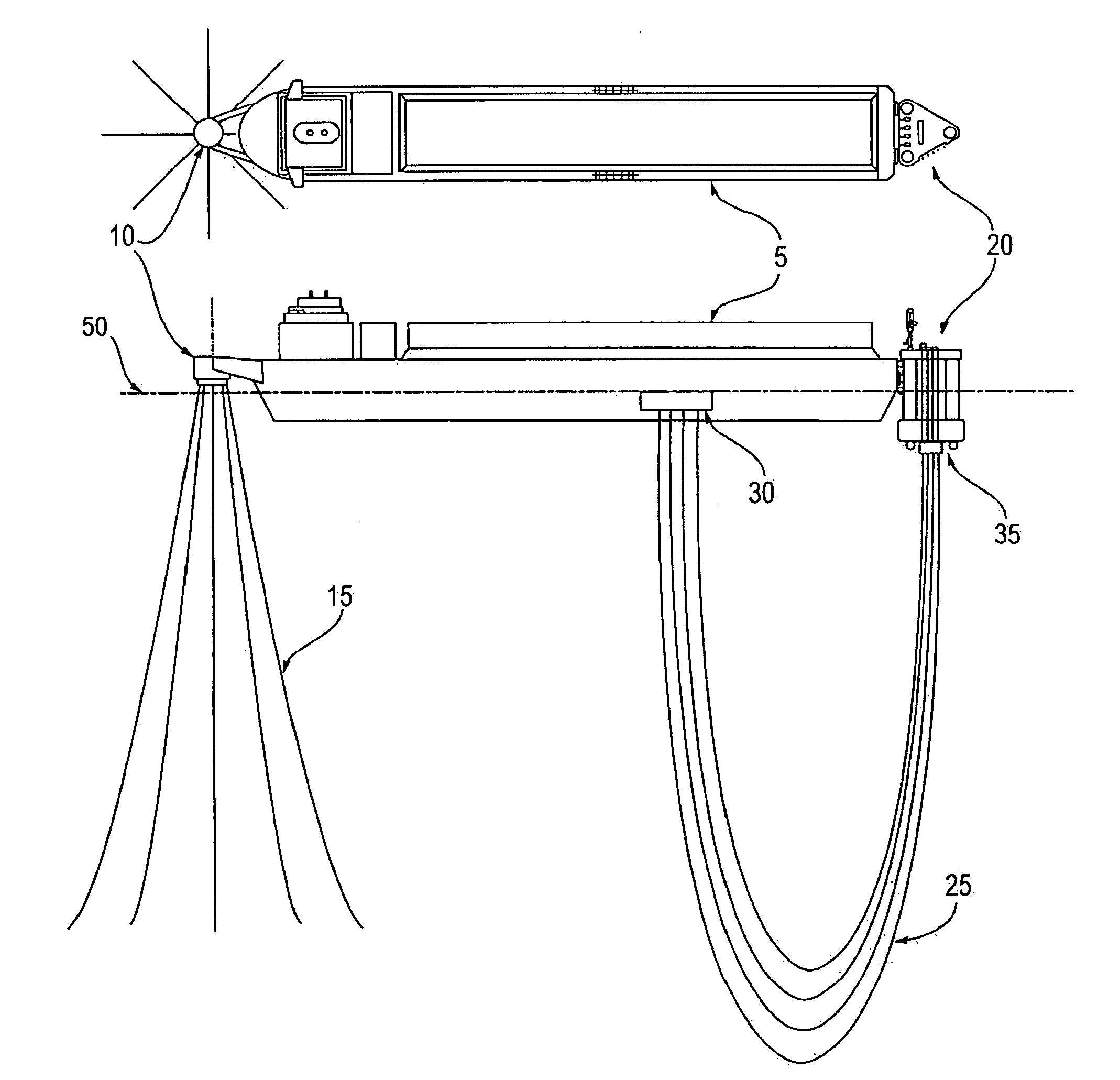
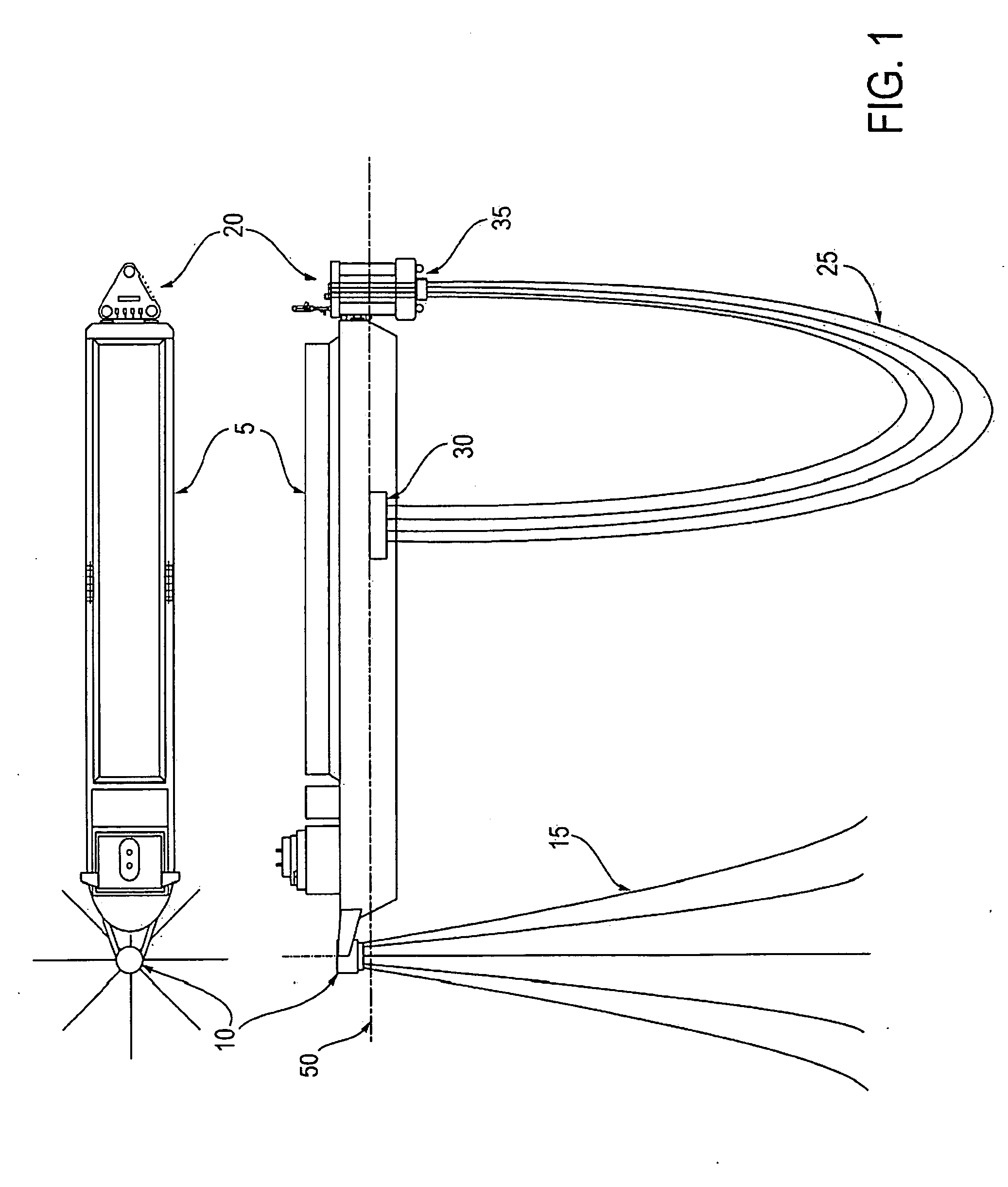
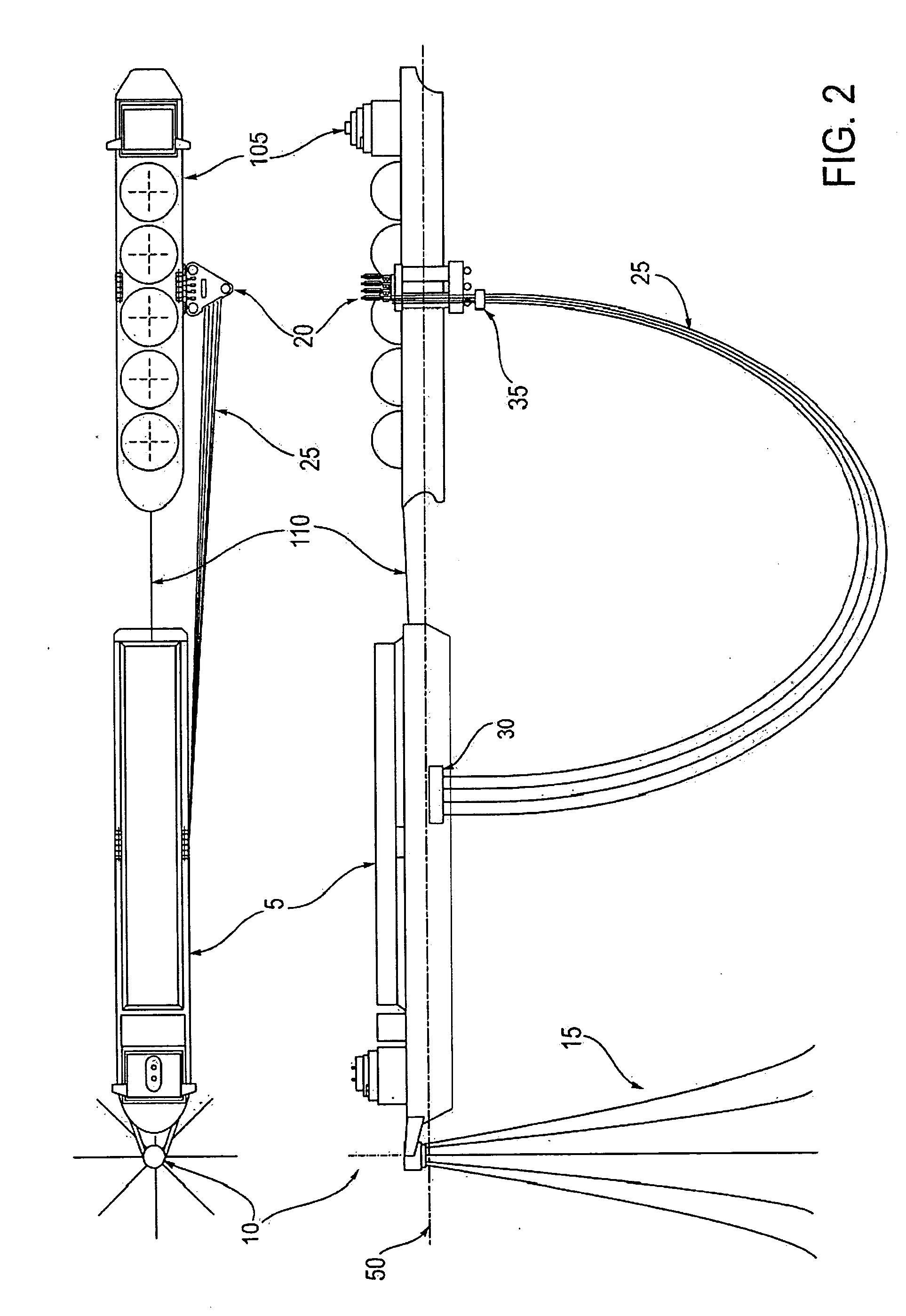
[0013]In an aspect of the invention, a transfer vessel includes: a floating vessel having a vertical portion; a fluid conduit disposed on the floating vessel; and a mooring device connected to the vertical portion for releasably mooring the transfer vessel to a surface of a second vessel, wherein the mooring device is capable of dampening the relative motions between the floating vessel and the second vessel.
[0014]In another aspect of the invention, a product transfer system includes: a first vessel; a transfer vessel comprising: a floating vessel having a vertical portion; a fluid conduit disposed on the floating vessel and in fluid communication with the first vessel; and a mooring device connected to the vertical portion for releasably mooring the transfer vessel to a surface of a second vessel, wherein the mooring device is capable of dampening the relative motions between the floating vessel and the second vessel.
[0015]In another aspect of the invention, a process for transferring a product between a first vessel and a second vessel includes: mooring a transfer vessel to a surface of a second vessel with a mooring device capable of dampening the relative motions between the transfer vessel and the second vessel; connecting a fluid conduit on the transfer vessel to the second vessel; and flowing product between the first vessel and the second vessel through the fluid conduit.
[0017]In another aspect of the invention, a process for recirculating a fluid product includes: mooring a transfer vessel to a surface of a product vessel with a mooring device capable of dampening the relative motions between the transfer vessel and the product vessel; connecting a fluid conduit on the transfer vessel to the product vessel; and recirculating the fluid product through the fluid conduit and the product vessel.

Problems solved by technology

Transferring fluids on the open ocean in unprotected locations offers particular hazards in terms of personnel safety and damage to the vessels or facilities involved.
No commercially proven technology exists that allows fluid transfer in harsh open ocean conditions between standard (non-dedicated) transport vessel and a floating storage vessel.
Commercially proven technologies exist for oil transfer in harsh open ocean conditions, but require dedicated transport carriers with extensive bow modifications.
Conversely, commercially proven technologies exist for oil transfer between a standard oil carrier and a floating storage vessel or SPM buoy, but not in harsh open ocean conditions; these systems cannot operate in harsh open ocean conditions due to marine operations issues and safety concerns with support vessels, i.e. tug boats and offshore service vessels.
No commercially proven system exists that can transfer fluids between a standard oil carrier and a floating storage vessel in harsh open ocean conditions.
Requiring protected fluid transfer sites limits the number of potential sites for new terminals, and in many regions a suitable site simply is not available.
Additionally, where the fluid to be transferred is hydrocarbon or petroleum based, public pressure is forcing the proposed fluid transfer facilities increasingly further offshore and to remote locations both onshore and offshore.
For example on the US West Coast, few shallow water sites are available and the Pacific Ocean Meteorological and Oceanographic (metocean) conditions (sea states, currents and winds) complicate the problem and further limit the number of potential solutions.
Loading arms have been proposed for fluid transfer between two vessels in a side-by-side berthing (mooring) arrangement, but have not been employed to date for a variety of reasons.
Being able to predict the relative motions between the vessels with the necessary high degree of certainty has proven to be difficult.
The mooring line arrangement in a side-by-side mooring is difficult at best in that the vessels are often very close in overall length, and thus proper bow and stern mooring line geometries can not be achieved.
Also, tug boat operational problems are further compounded by the approach layout in a side-by-side berthing.
Additional concerns include damage to the vessels due to high relative motions between the vessels, and increased potential for breakout due to high loads on the mooring lines.
It has been found that these systems can require the use of specially designed (dedicated) transport carriers, can be overly complicated and expensive, difficult to operate in other than benign weather conditions, and in some cases can require the use of technology that is not widely endorsed by the maritime industry.
More specifically, none of these systems have solved the problem of how to safely deliver and connect the fluid transfer hose, pipe or conduit between vessels in harsh open ocean conditions.
Hose manufactures have only recently begun work to explore ways to retrieve / deploy the hose between liftings, but difficulties remain with all of these concepts.
In particular, the means of lifting the hoses out of the water and connecting them to the floating transport vessel manifold and supporting them during the transfer operation is problematic and has yet to be defined.
Moreover, how to manage the hoses during an emergency disconnect is likewise unresolved.

Method used


Image

  • Process, vessel and system for transferring fluids between floating vessels using flexible conduit and releasable mooring system
  • Process, vessel and system for transferring fluids between floating vessels using flexible conduit and releasable mooring system
  • Process, vessel and system for transferring fluids between floating vessels using flexible conduit and releasable mooring system

Examples


Embodiment Construction

[0024]In this disclosure, the term fluid refers to liquefied natural gas, liquefied heavy gas, liquefied petroleum gas, crude oil, diesel, syncrude, petroleum condensate, synthetic lube oil, naphtha, methanol and mixtures of the same.

[0025]Liquefied natural gas (LNG) is a cryogenic fluid comprising predominately methane (C1) with decreasing amounts of C2+ hydrocarbons, and is sufficiently cold to remain liquid at near atmospheric pressures. Liquefied heavy gas (LHG) is a cryogenic fluid comprising predominately C1 hydrocarbons, with lesser amounts of C2's thru C4's, and with decreasing amounts of C5's+ hydrocarbons, but requires pressurization (often between 500 and 750 psig) to remain liquid at temperatures well above that of LNG. Liquefied petroleum gas (LPG) is a near-cryogenic fluid comprising predominately C3 and C4 hydrocarbons, which can either be refrigerated to remain liquid at near atmospheric pressures or pressurized to remain liquid at atmospheric temperature. All of the...


PUM


Abstract

A system is provided for transferring fluids such as liquefied natural gas between a floating transport vessel and a floating storage vessel utilizing a transfer vessel to deploy, operate and return a fluid conduit to the storage vessel. The fluid is transferred through at least one submerged-subsea catenary flexible conduit, at least one floating flexible conduit, or any combination thereof. A transfer vessel, including a releasable mooring system, is provided for deploying the conduit from the storage vessel to the transport vessel, mooring with a transport vessel, maintaining a unified connection during fluid transfer, releasing the mooring once fluid transfer is completed, returning to and parking on the storage vessel, and storing the conduit between fluid transfers. The transfer vessel and releasable mooring system allows safe, controlled operation and fluid transfer in open sea conditions.

Description

FIELD OF THE INVENTION[0001]The present invention relates to a transport vessel with a fluid transfer conduit and a releasable mooring system that enables fluid transfer between floating vessels in open sea conditions. More particularly, the present invention relates to a system for mooring a transfer vessel to another vessel for the purpose of transferring fluids between vessels.BACKGROUND OF THE INVENTION[0002]Transferring fluids on the open ocean in unprotected locations offers particular hazards in terms of personnel safety and damage to the vessels or facilities involved. The fluids which are transported in a transport vessel from a remote location may be delivered to either a tank located at the offshore facility, or by pipeline to a land-based receiving terminal. Offshore tank storage facilities may either be floating or settled on the seafloor.[0003]No commercially proven technology exists that allows fluid transfer in harsh open ocean conditions between standard (non-dedica...

Claims


Application Information

Patent Timeline
Patent Type & Authority Applications(United States)
IPC IPC(8): B63B22/02
CPCB63B22/021B63B27/24Y10T137/87973
Inventor ADKINS, JIMMIE DEANHARTONO, JOHN S.MCDONALD, DAVID T.
Owner CHEVROU USA INC
Learn More