
Tactile tile with improved reinforced embedment plate

a technology of reinforced embedment and tile, which is applied in the direction of single unit paving, physical therapy, and walkways, etc., can solve the problems of reducing the service life of the dome, so as to minimize the long-term maintenance cost, minimize installation time and cost, and facilitate installation.

Active Publication Date: 2008-10-02
METADOME
View PDF25 Cites 30 Cited by
  • Summary
  • Abstract
  • Description
  • Claims
  • Application Information

AI Technical Summary

Benefits of technology

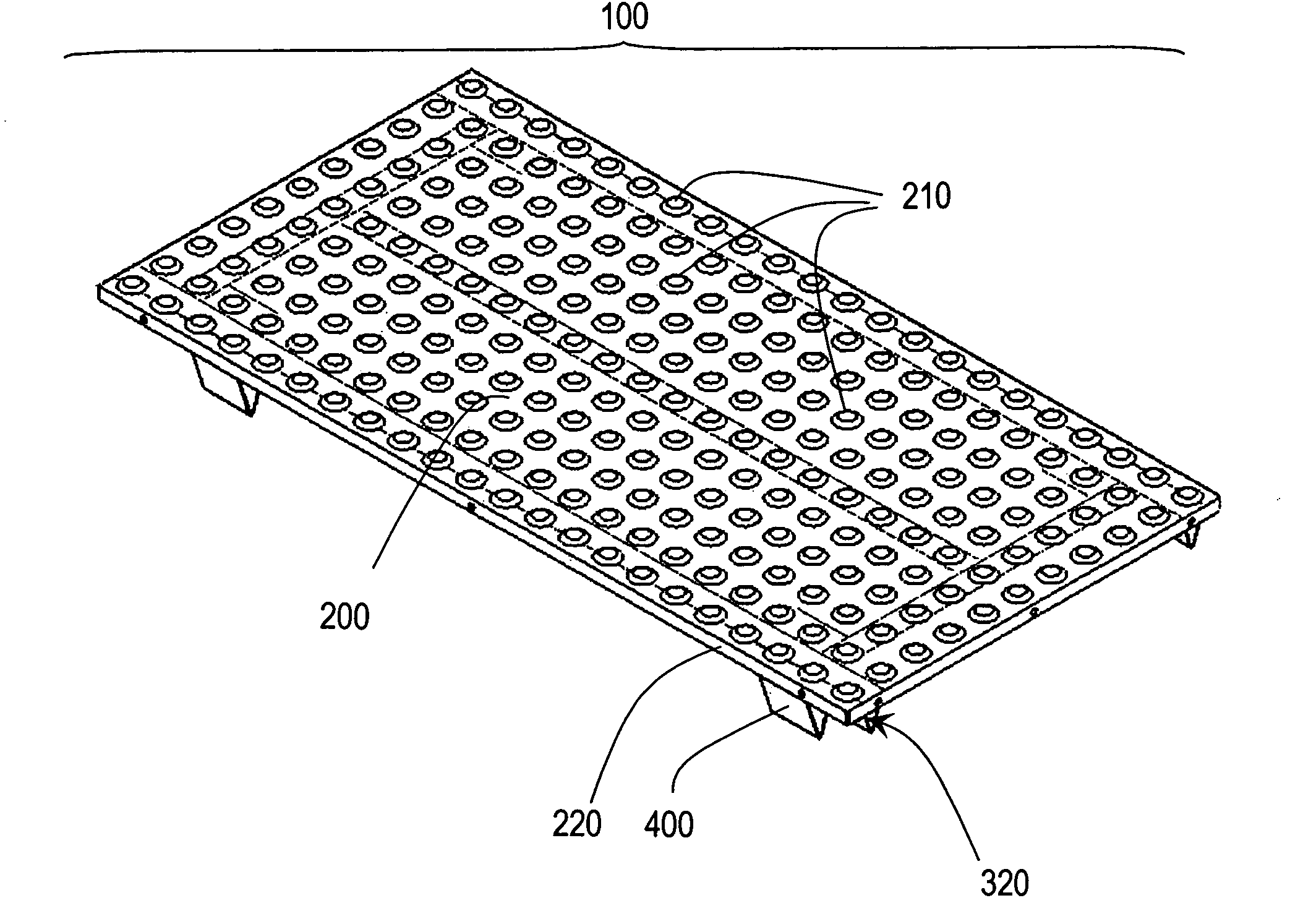
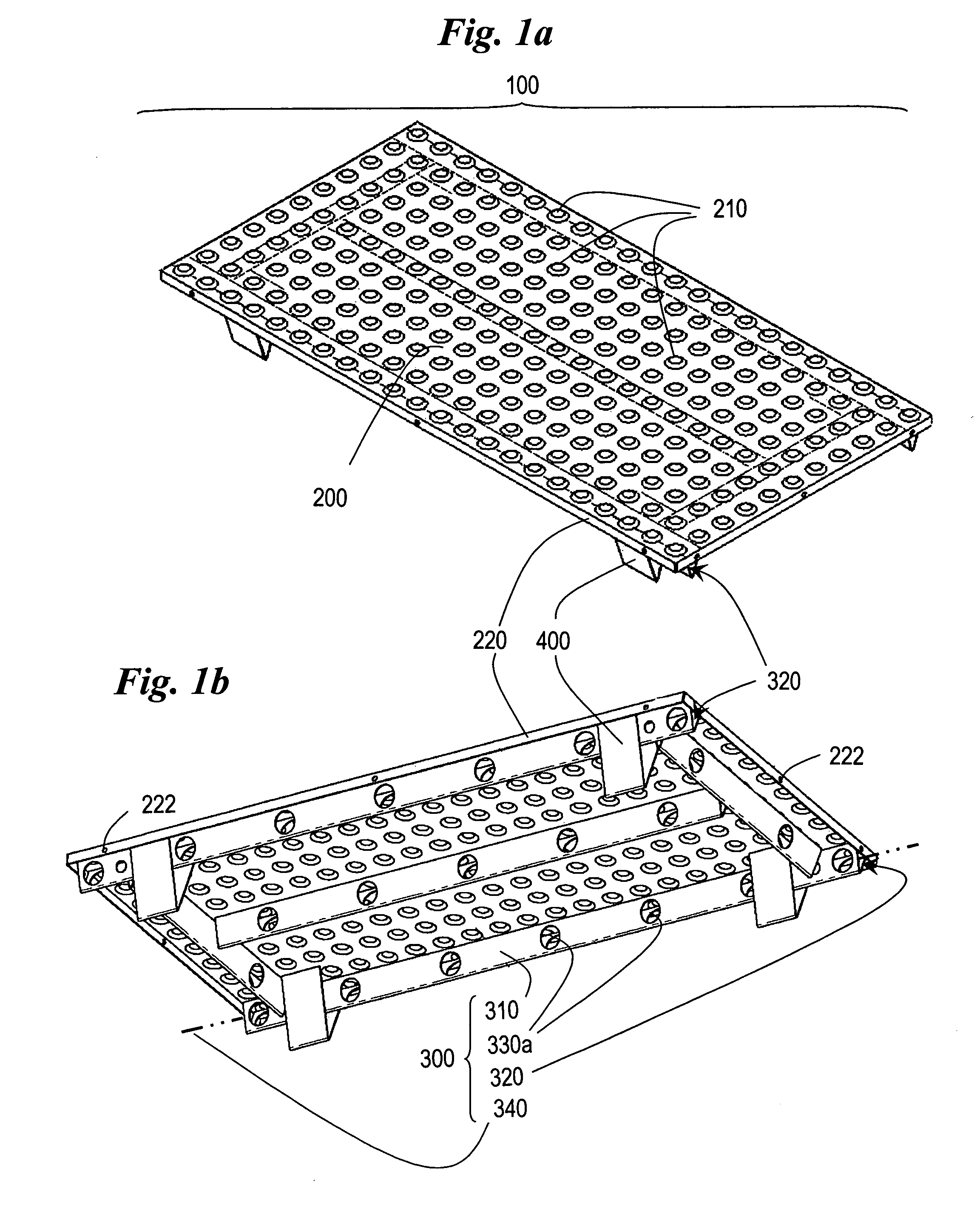
[0009]The present invention is directed to an embedment tile and method that satisfy this need for a device that is designed to be both easily installable to minimize installation time and cost, and durable to minimize long-term maintenance costs and to reliably provide tactilely detectable warning surfaces. Cross beams with hollow chambers are provided on the underside of the embedment tile of the present invention to enable movement of air and moldable material into the interior of the cross beams during installation thus enabling air release as well as movement of moldable material internal to the tile's cross beams. In this way, the formation of air pockets under the tile member that might otherwise resist embedment of the tile, and prevent the material from flowing smoothly to fill the spaces between the cross beams and under the lower surface of the tile more completely, is minimized. Once set, the moldable material internal to the cross beams serves to further secure the tile in place in the walkway.
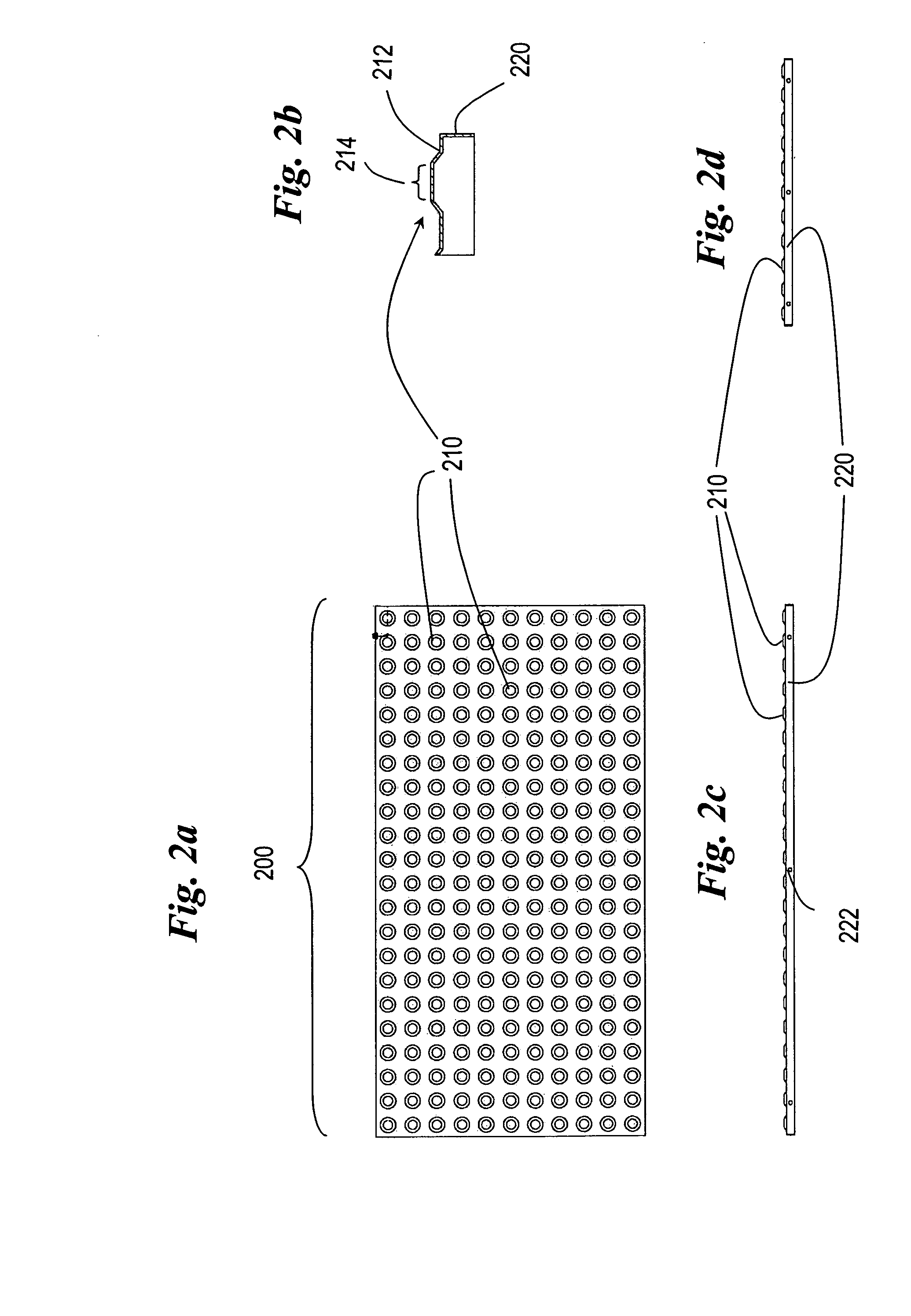
[0010]One version of the embedment tile for embedment in a moldable material such as concrete or asphalt, comprises a tile member substantially planar in form, having an upper surface and a lower surface and two or more sides defining side edges, the upper surface having a plurality of projections extending upward there from in a tactilely detectable pattern; and, two or more cross beams projecting downward a distance from the lower surface of the tile member, each cross beam comprising a hollow chamber and a sidewall, the sidewall having two sides defining side edges and two ends defining a length of the cross beam there between, each sidewall being shaped so as to define the hollow chamber interior to and running the length of each cross beam and so as to define an opening at each end, the hollow chamber of each cross beam being in communication with an exterior via the opening at each end so as to allow air and moldable material located under the tile member to move into the hollow chambers of the cross beams during embedment of the tile in the moldable material, whereby an embedment tile is provided with cross beams having hollow chambers that allow for air release and movement of moldable material internal to the cross beams of the tile during embedment so as to ease and speed installation and to secure embedment of the tile into the moldable material.
[0011]In another version, air release means are provided for enhancing communication between the hollow chamber of one or more of the cross beams and the exterior so as to further enable air and moldable material to move into the hollow chamber from the exterior via said air release means during installation of the tile. The air release means may consist of one or more apertures located in the sidewall of the one or more cross beams. Alternatively, the air release means may consist of a gap formed where one side edge of the sidewall of each of said one or more cross beams approaches but does not attach to the lower surface of the tile member, the space between said side edge and the lower surface of the tile member defining the gap, the opposing edge of the sidewall connecting the cross beam to the lower surface of the tile member.

Problems solved by technology

However, most of these devices are made out of plastic and are flimsy, being subject to ultraviolet light damage, deterioration and cracking in short periods of time.
Also, inherent to the truncated dome design is the exposure of domes to severe impacts by snowplow equipment, particularly snowplow blades and end-loader buckets.
Domes made of plastic tend to be sheared off, nicked or cracked when snowplows hit them.
The fact that plastic embedded tile devices are easily damaged results in high long-term costs to maintaining truncated dome surfaces when they are employed.
Yet, current manufactures of plastic embedded tile devices either do not warrant the devices or warrant them for no more than five years.
Public entities cannot afford to replace truncated dome devices every five years—nor every ten to fifteen years for that matter.
However, each one of these references suffers from one or more of the following disadvantages: (1) they do not enable embedment of a tile in moldable materials such as concrete or asphalt; (2) they lack means for securely interlocking a tile with the moldable material; (3) they result in build-up of moldable material around the edges of the tile when inserted, resulting in longer installation times due to the need for removal of the buildup prior to finishing; (4) the tiles do not provide means for internal air release and therefore allow trapped air pockets to obstruct the efficient movement of air and moldable material when the tile is sunk, making embedment more time-consuming and difficult, and often requiring the application of weights to prevent the tile from floating while the moldable material sets; and, (5) the tiles are not made of materials that stand up to the cracking and sheering effects of snowplows or other heavy equipment, thus resulting in high maintenance costs over time.

Method used


Image

  • Tactile tile with improved reinforced embedment plate
  • Tactile tile with improved reinforced embedment plate
  • Tactile tile with improved reinforced embedment plate

Examples


Embodiment Construction

[0065]Referring now specifically to the figures, in which identical or similar parts are designated by the same reference numerals throughout, a detailed description of the present invention is given. It should be understood that the following detailed description relates to the best presently known embodiment(s) of the invention. However, the present invention can assume numerous other embodiments, as will become apparent to those skilled in the art, without departing from the appended claims. For example, though the present embedment tile is described relative to embedment in moldable materials such as concrete or asphalt, it may also be embedded in other types of materials. Also, though the tactilely detectable surface of the embedment tile is described as producing a warning pattern compliant with ADA Accessibility Guidelines, any pattern may be produced, including way-finder patterns, purely decorative patterns, emblematic patterns or patterns of other sorts.

[0066]It should als...


PUM


Abstract

Disclosed is an embedment tile for producing a tactilely detectable surface in a moldable material and method for using same. The tile comprises a tile member having a pattern of upwardly extending projections on its upper surface forming a tactilely detectable pattern, and a cross beam joined to the lower surface of the tile member. The cross beam defines a hollow chamber and apertures to allow for the release of air and inflow of moldable material to secure the embedment tile when the moldable material hardens. The cross beam can define a lower open portion at a cross beam end portion that eases installation by permitting a more direct flow path into the chamber for moldable material. The embedment tile can also include a reinforcing member joined to the lower surface of the tile member and / or a transverse reinforcing member joined to a lower surface of the tile member.

Description

[0001]This is a continuation-in-part application of pending U.S. application Ser. No. 11 / 371,550 filed Mar. 9, 2006, which was a continuation-in-part of U.S. application Ser. No. 10 / 951,240 filed Sep. 27, 2004, now abandoned, and which claims the benefit of U.S. Provisional Application No. 60 / 660,529 filed Mar. 10, 2005, all of which are incorporated herein by reference.FIELD AND BACKGROUND OF THE INVENTION[0002]The Department of Justice (DOJ), the lead agency that oversees the Americans with Disabilities Act (ADA), has mandated that many municipalities and other governmental bodies comply with certain regulations regarding accessibility. One such regulation deals with accessibility on walkways in public right of ways. In brief, it requires that surfaces of those walkways enable tactile detection by visually impaired persons.[0003]One of the primary ways of providing the ability to detect proximity to hazardous locations (e.g., roadways, railroad crossings, etc.) is by modifying the...

Claims


Application Information

Patent Timeline
Patent Type & Authority Applications(United States)
IPC IPC(8): E04F11/16
CPCA61H3/066E01C5/16E01C5/22E04F15/02
Inventor SIPPOLA, DUANE F.
Owner METADOME
Learn More