
Apparatus and method for operating relay link in relay broadband wireless communication system

a broadband wireless communication and relay technology, applied in the field of relay broadband wireless communication system, can solve the problems of reducing the amount of usable resources in communication between the bs and other mobile stations, unable to provide smooth services for a plurality of relay stations, and unable to perform simultaneous transmission and reception using the same frequency. , to achieve the effect of reducing the overhead of resources

Inactive Publication Date: 2008-09-25
SAMSUNG ELECTRONICS CO LTD
View PDF6 Cites 70 Cited by
  • Summary
  • Abstract
  • Description
  • Claims
  • Application Information

AI Technical Summary

Benefits of technology

[0008]To address the above-discussed deficiencies of the prior art, it is a primary of the present invention is to substantially solve at least the above problems and / or disadvantages and to provide at least the advantages below. Accordingly, an object of the present invention is to provide an apparatus and method for reducing a resource overhead caused by relay communication in a relay broadband wireless communication system.
[0009]Another object of the present invention is to provide an apparatus and method for reducing the number of relay stations required for relay communication in a relay broadband wireless communication system.
[0010]Another object of the present invention is to provide an apparatus and method for causing a radio station to selectively connect to a plurality of base stations in a relay broadband wireless communication system.

Problems solved by technology

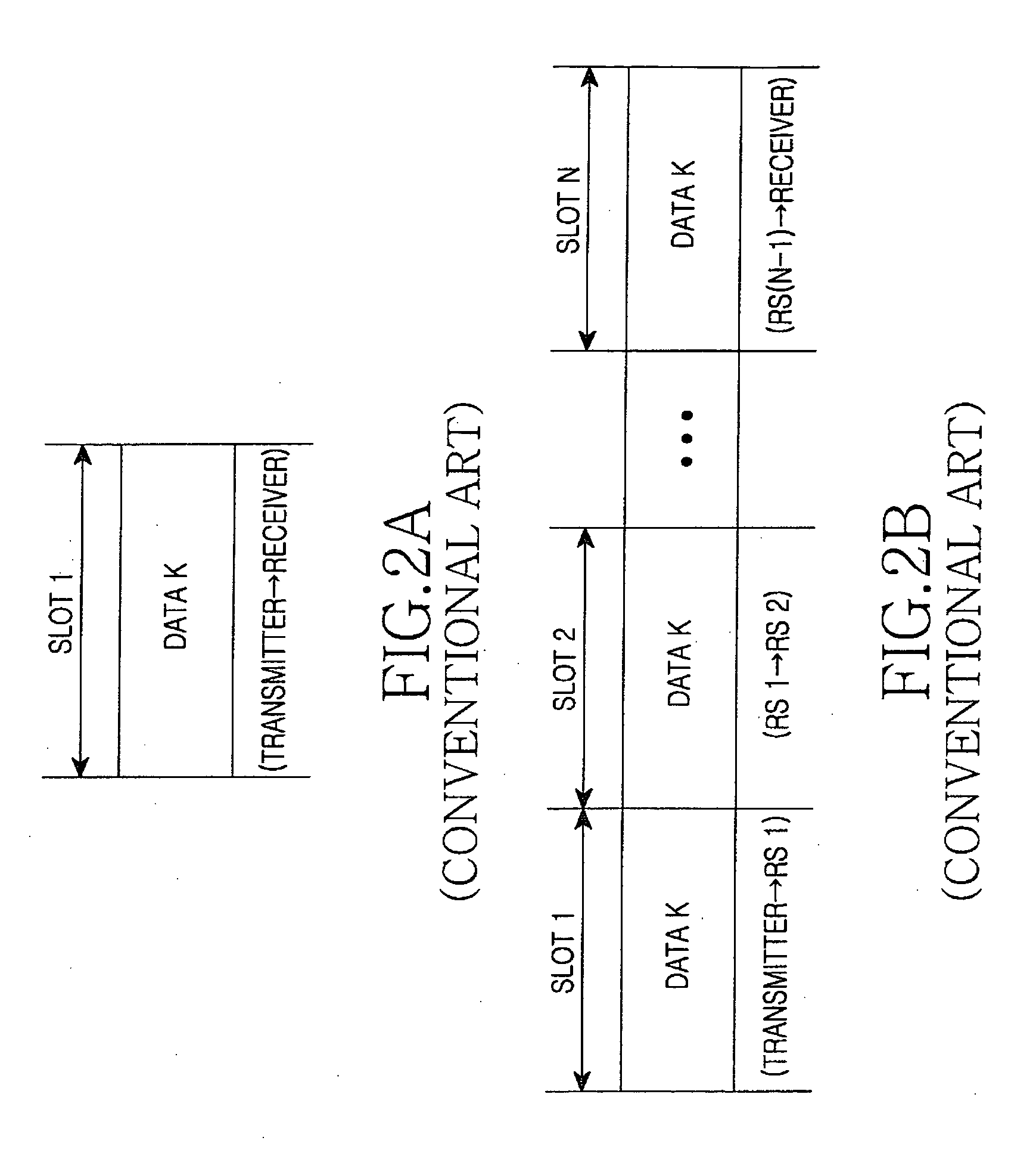
The RS cannot perform simultaneous transmission and reception using the same frequency.
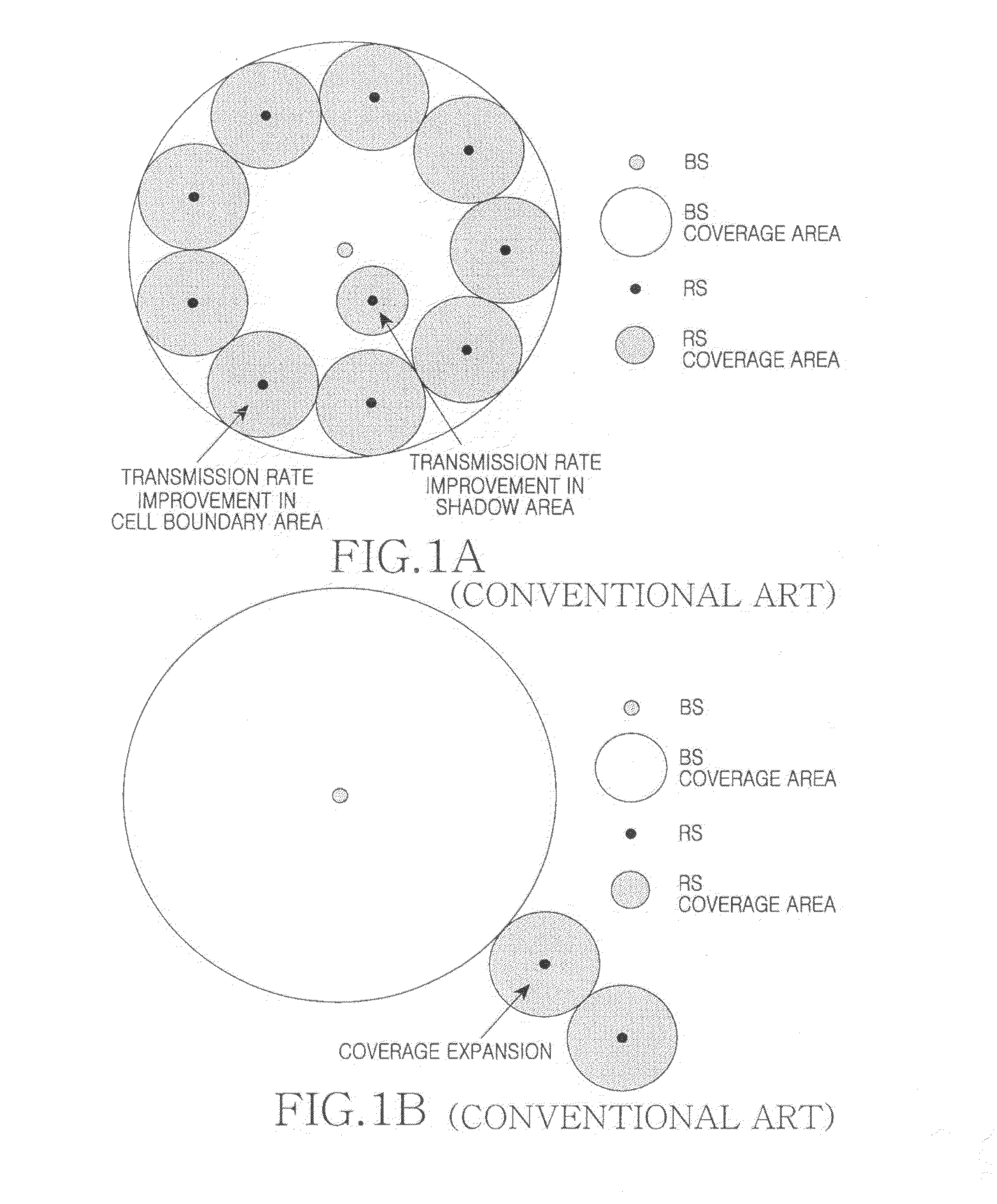
The radio resources being consumed in communication between the BS and the RS act as a huge overhead, thereby reducing the amount of usable resources in communication between the BS and other mobile stations.
A plurality of relay stations fail to provide smooth services if sufficient resources are not ensured in the link between the BS and the RS and the link between the relay stations.
Also, an increase in system capacity cannot be expected because of the overhead caused by resource consumption of the plurality of relay stations.
Thus, the RS installation cost increases.

Method used


Image

  • Apparatus and method for operating relay link in relay broadband wireless communication system
  • Apparatus and method for operating relay link in relay broadband wireless communication system
  • Apparatus and method for operating relay link in relay broadband wireless communication system

Examples


Embodiment Construction

[0030]FIGS. 3 through 9, discussed below, and the various embodiments used to describe the principles of the present disclosure in this patent document are by way of illustration only and should not be construed in any way to limit the scope of the disclosure. Those skilled in the art will understand that the principles of the present disclosure may be implemented in any suitably arranged wireless communication system.

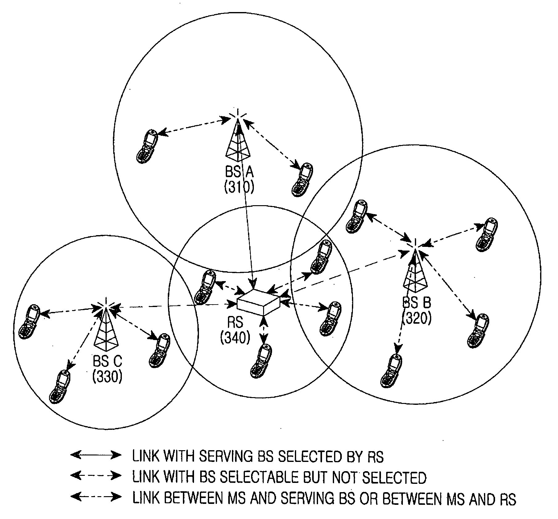
[0031]A technique for causing a relay station (RS) to select a serving base station (BS) in a relay broadband wireless communication system according to the present invention will be described. An orthogonal frequency division multiplexing (OFDM) wireless communication system is described as an example in the following description. However, the present invention is not limited thereto but is applicable to other types of wireless communication systems in the same manner.

[0032]The cell configuration proposed according to the present invention will now be briefly describe...


PUM


Abstract

Provided is a relay broadband wireless communication system. The relay broadband wireless communication system includes a plurality of base stations, and one or more relay stations. The base stations perform communication with a relay station placed within a coverage area and generate state information to be provided to the relay station. The one or more relay stations are disposed at a location allowing communication with the plurality of base stations and select one or more serving base stations based on state information received from each of the base stations.

Description

CROSS-REFERENCE TO RELATED APPLICATION(S) AND CLAIM OF PRIORITY[0001]The present application claims priority under 35 U.S.C. §119 (a) to an application filed in the Korean Intellectual Property Office on Mar. 21, 2007 and allocated Serial No. 2007-27716, the contents of which are incorporated herein by reference.TECHNICAL FIELD OF THE INVENTION[0002]The present invention relates generally to a relay broadband wireless communication system, and in particular, to an apparatus and method for operating a relay link in a relay broadband wireless communication system.BACKGROUND OF THE INVENTION[0003]Multi-hop relaying is drawing much attention as a technology that can expand cell coverage at a low cost in a cellular system and provide users with high transmission rate. Representatively, IEEE 802.16j relay task group is standardizing mobile multihop relay (MMR), and developed laboratories and enterprises studying 4th generation (4G) mobile communications around the world are competitively ...

Claims


Application Information

Patent Timeline
Patent Type & Authority Applications(United States)
IPC IPC(8): H04B7/14
CPCH04B7/2606H04B7/155H04B7/14
Inventor SHIN, OH-SOONYUN, SANG-BOH
Owner SAMSUNG ELECTRONICS CO LTD
Learn More