Electromagnetic Relay

a technology of electromagnetic relay and insertion hole, which is applied in the direction of electrical apparatus casing/cabinet/drawer, circuit-breaking switch, hermetically sealed casing, etc., can solve the problems of difficult to insert each hook into each hole, card may accidentally drop from the movable spring, and difficulty in inserting the hook into the insertion hole. , to achieve the effect of easy elastic deformation, small force and easy elastic deformation

Active Publication Date: 2008-09-25
MATSUSHITA ELECTRIC WORKS LTD
View PDF8 Cites 4 Cited by
  • Summary
  • Abstract
  • Description
  • Claims
  • Application Information

AI Technical Summary

Benefits of technology

[0011]Preferably, the card has a recess in the inner surface of the insertion hole, and the recess runs along an axial direction of the insertion hole so that the one end of the movable spring pushed by the inner surface of the insertion hole and elastically deformed in passing the insertion hole can escape to the recess. Such a recess allows the movable spring to be easily elastically deformed, whereby it becomes possible to insert the movable spring into the card with smaller force.
[0012]More preferably, the movable spring has slits on both sides of the hook. Such slits allow the hook to be easily elastically deformed, whereby it becomes possible to insert the movable spring into the card more easily.
[0013]Preferably, the card has a step on the inner surface of the insertion hole, and the end of the hook is engaged with a surface of the step opposite to a side from which the one end of the movable spring is inserted. In this case, it is possible to lower the height of the electromagnetic relay, as compared with a case that the hook is engaged with a surface of the card opposite to a side from which the one end of the movable spring is inserted.
[0014]Furthermore, preferably, a surface of said step on the side from which the one end of the movable spring is inserted is inclined toward an inside of the insertion hole. In this case, it is possible to guide the movable spring into the insertion hole easily when the movable spring is inserted into the insertion hole.
[0015]Preferably, the movable spring has a shoulder part for supporting a surface of the card on a side from which the one end of the movable spring is inserted, and the shoulder part is formed into a U-shape by bending a part of the movable spring toward the opposite end side. In this case, it is possible to reduce the friction between the shoulder part and the card, and it is possible to prevent deterioration of the reliability of the contacts caused by adhesion of the abrasion powder generated by the friction between the shoulder part and the card to the movable and fixed contacts.
[0016]The number of the contact mechanisms is not limited to one, but the electromagnetic relay of the present invention may have two or more contact mechanisms. In this case, preferably, the card has a plurality of insertion holes to which the one end of each of the movable springs is inserted, and the insertion holes comprise a first insertion hole and a second insertion hole. The first insertion hole has a step on an inner surface thereof, and the hook of the movable spring inserted into the first insertion hole is engaged with a surface of the step opposite to a side from which the one end of the movable spring is inserted, and the second insertion hole has no step to which the hook of the movable spring is engaged, and the card is not restrained by the hook inserted into the second insertion hole. In a manufacturing process, after a relay was assembled and its operation is checked, the relay may be taken apart to adjust the distance between the movable contact and the fixed contact. If every hook of the movable springs is engaged with the card, it may take a lot of trouble to detach the card from the movable springs, whereby worker efficiency may be lowered. So, by forming the first and second insertion holes as the insertion hole, and engaging the hook inserted into the first insertion hole to the step in the first insertion hole but not engaging the hook inserted into the second insertion hole, it becomes easy to detach the card from the movable springs if necessary, while preventing the accidental drop of the card.

Problems solved by technology

However, in the electromagnetic relay, there was a fear that the card may accidentally drop from the movable spring.
However, in the case where the hook was bent at 90 degrees, like the above electromagnetic relay, it was difficult to insert the hook into the insertion hole.
Especially, in a case where a plurality of movable springs were aligned along a moving direction of the card, it was very difficult to insert each hook into each hole.
However, in the above case, there was a problem that it was difficult to insert the hooks into the insertion hole, because the edges of the hooks 101 got in touch with the insertion hole when the hooks 101 were inserted into the insertion hole, and the friction between the hooks 101 and the insertion hole was large.

Method used


Image

  • Electromagnetic Relay
  • Electromagnetic Relay
  • Electromagnetic Relay

Examples


Embodiment Construction

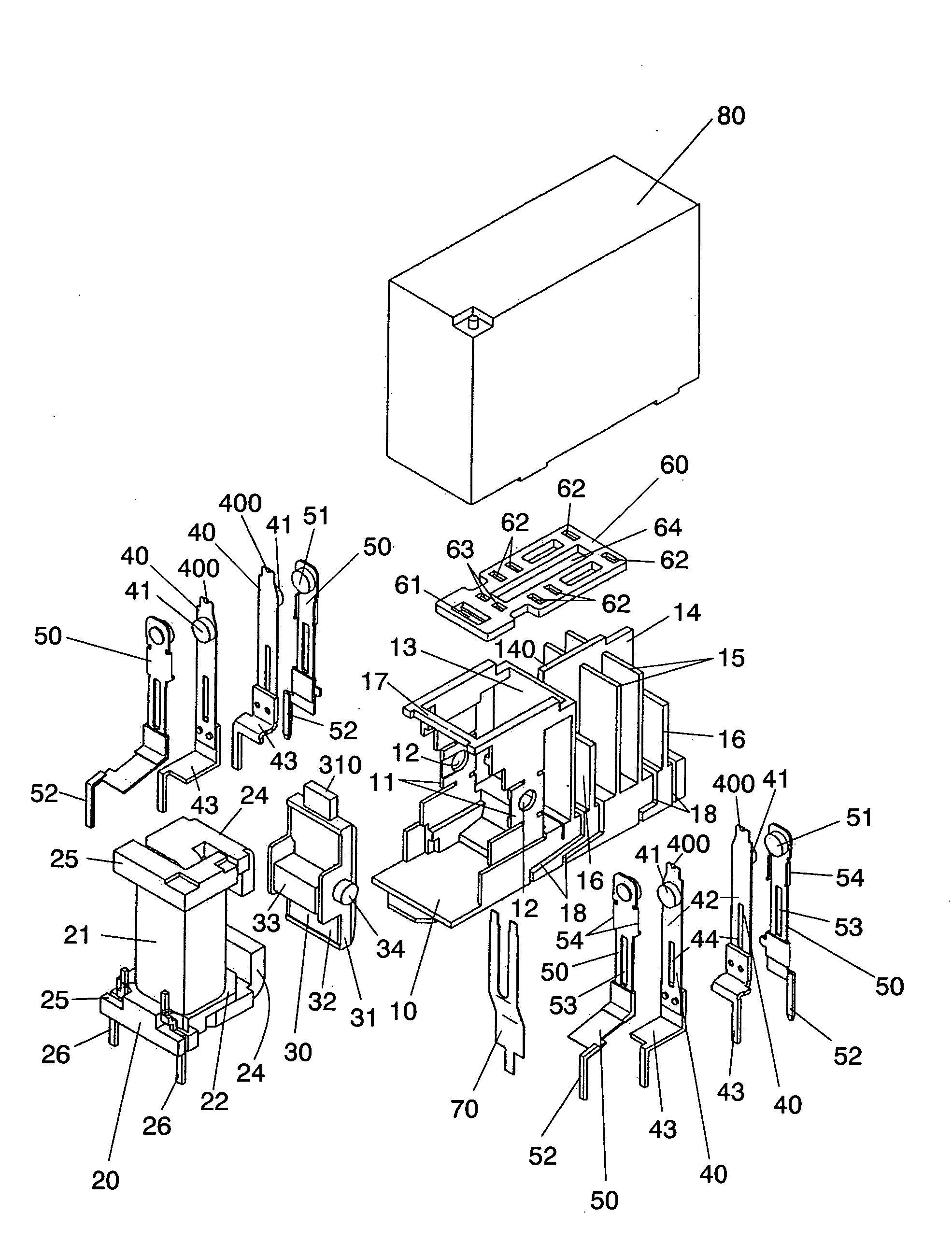
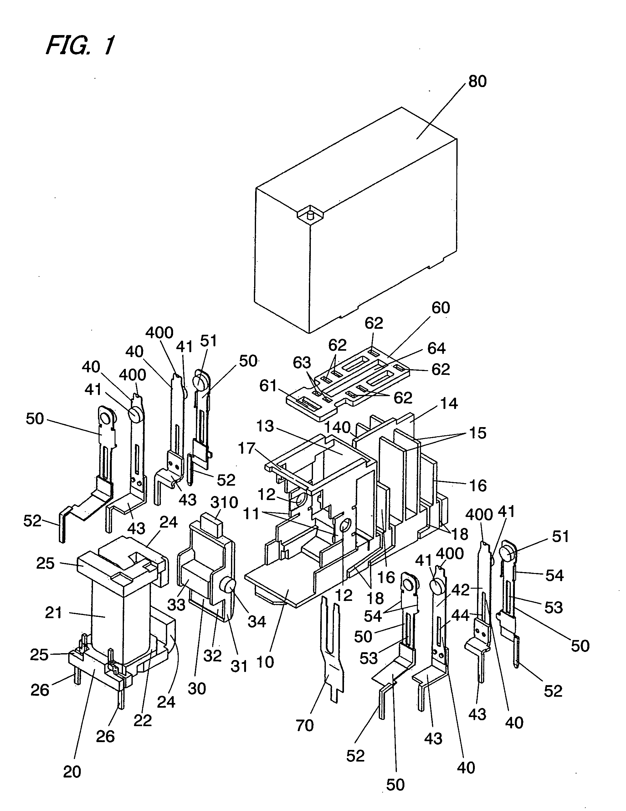
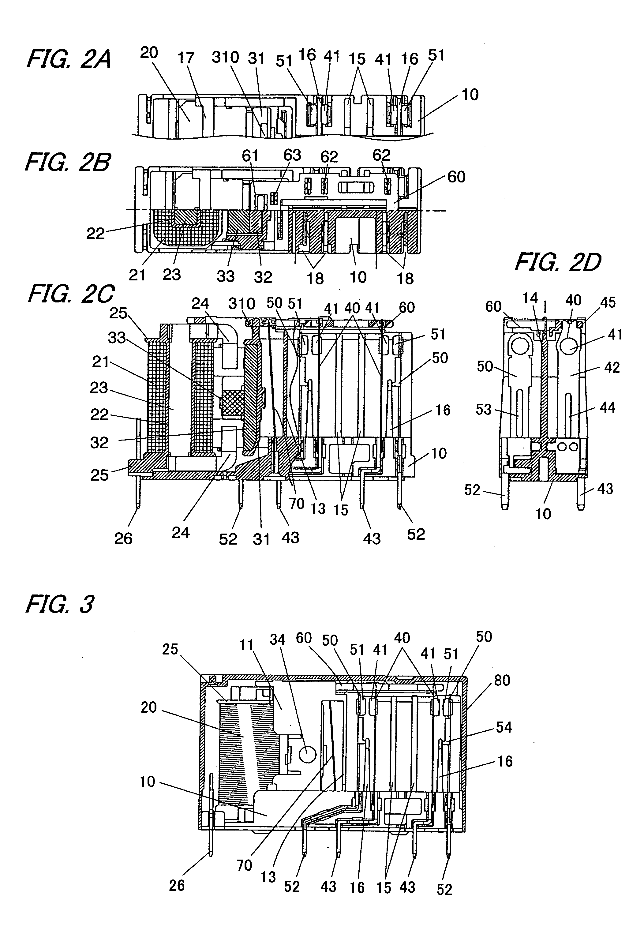
[0043]Hereinafter, the present invention will be described in more detail with reference to the accompanying drawings. In the following explanation, upward and downward directions are related with reference to FIG. 3. FIG. 1 is an exploded perspective view of an electromagnetic relay in accordance with an embodiment of the present invention. This electromagnetic relay is a multipole electromagnetic relay having two normally open contacts and two normally closed contacts.

[0044]The electromagnetic relay comprises a base 10, an electromagnet 20, an armature 30, four movable springs 40 each having a movable contact 41 at its one end, four fixed springs 50 each having a fixed contact at its one end, a card 60, a return spring 70, and a cover 80.

[0045]The base 10 is a plastic molding and has a pair of side walls 11 and a plurality of insulating walls 13-16 molded in one piece. The base 10 is roughly divided into a first area where the electromagnet 20, the armature 30, and the return spri...


PUM


Abstract

The electromagnetic relay of the present invention comprises a base (10), an electromagnet (20) disposed on the base, an armature (30) supported rotatably by the base, a movable spring (40) whose one end has a movable contact (41) and the opposite end is secured to the base, a fixed contact (51) disposed opposite to the movable contact, and a card (60). The card has a coupling part (61) to be coupled to the armature and an insertion hole (62) to which the one end of the movable spring is inserted, and it deforms the movable spring elastically in conjunction with a swing motion of the armature to selectively open or close a connection between the movable contact and the fixed contact. The movable spring has a U-shaped hook formed by bending the one end of the movable spring toward the opposite end side, and the hook can pass through the insertion hole while being pushed by an inner surface of the insertion hole and being deformed elastically, and an end of the hook is engaged with the card.

Description

TECHNICAL FIELD[0001]The present invention relates to an electromagnetic relay.BACKGROUND ART[0002]Japanese Non-examined Patent Publication No. 11-339624 discloses an electromagnetic relay which links a rotation of an armature with a rotation of a movable spring through a card and makes a movable contact, provided on the movable spring, come into contact with or separate from a fixed contact in conjunction with the rotation of the armature. In this electromagnetic relay, the card has an insertion hole, and the movable spring is coupled to the card with its tip inserted into the insertion hole.[0003]However, in the electromagnetic relay, there was a fear that the card may accidentally drop from the movable spring.[0004]Japanese Non-examined Patent Publication No. 11-102631 discloses an electromagnetic relay which has a hook formed by bending a tip of the movable spring at about 90 degrees at the tip of the movable spring and engages the hook to a periphery of the insertion hole to pr...

Claims


Application Information

Patent Timeline
Patent Type & Authority Applications(United States)
IPC IPC(8): H01H3/00
CPCH01H50/026H01H50/042H01H2001/265H01H51/2272H01H51/24H01H50/642
Inventor KATOU, YOSHIMASA
Owner MATSUSHITA ELECTRIC WORKS LTD
Why Eureka
Try Eureka