
Quick Connector for High Pressure Applications

a technology for high-pressure applications and connectors, which is applied in the direction of hose connections, couplings, pipes, etc., can solve the problems of increasing the difficulty of maintaining a fluid tight join

Active Publication Date: 2008-09-25
TI GRP AUTOMOTIVE SYST LLC
View PDF32 Cites 9 Cited by
  • Summary
  • Abstract
  • Description
  • Claims
  • Application Information

AI Technical Summary

Benefits of technology

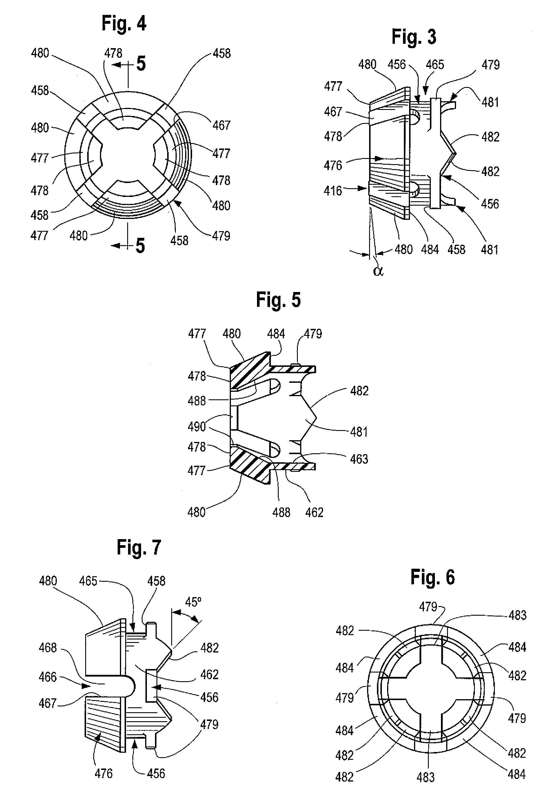
[0007]This invention is directed to an improved sleeve or outer spacer that is configured to transfer axial load imparted by the O-ring seal directly to the locking arms of the retainer. Also disclosed is an improved form of insertion verifier / latch that serves the functions of providing verification of the complete insertion of the male member into the body of the connector assembly, and also provides a latching function to stabilize the locking arms of the tube retainer to suppress inward movement and increase overall burst pressure performance. The insertion verifier / latch also serves to close the entrance into the connector body to minimize entry of contaminants.

Problems solved by technology

Also, such quick connector assemblies are often used in applications where the components are subject to high temperature or pressure, as well as vibration and cyclic application of pressure.
These conditions increase the difficulty of maintaining a fluid tight joint.

Method used


Image

  • Quick Connector for High Pressure Applications
  • Quick Connector for High Pressure Applications
  • Quick Connector for High Pressure Applications

Examples


Embodiment Construction

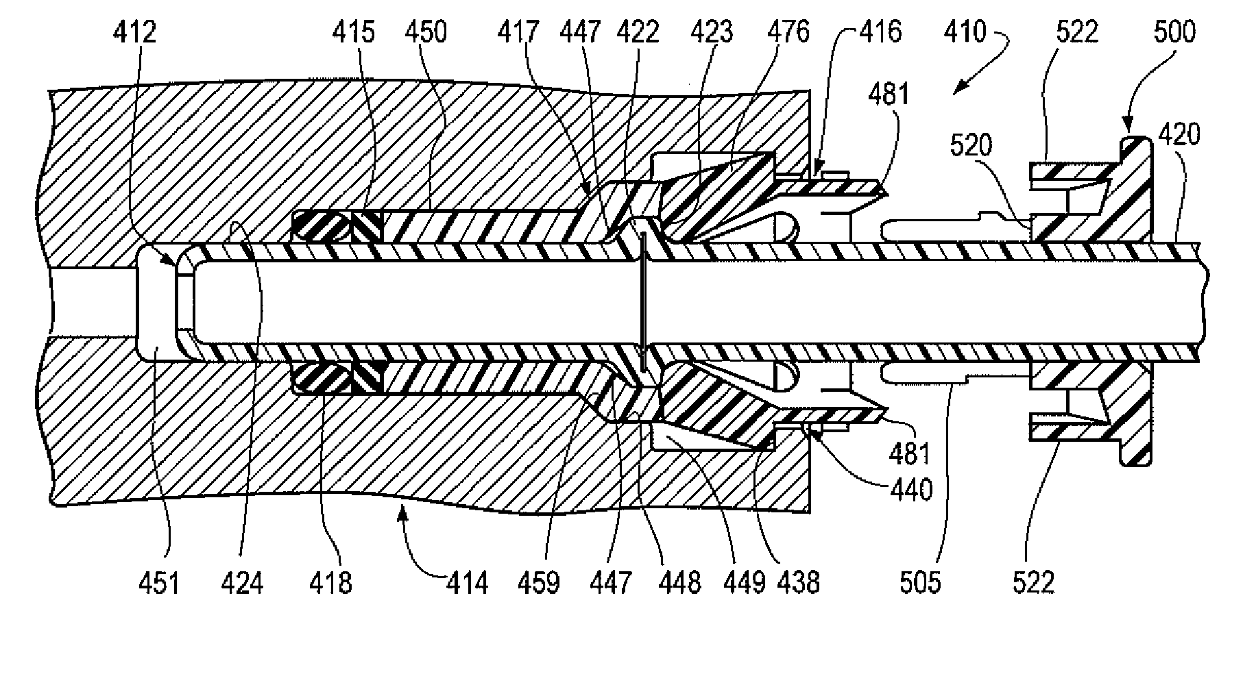
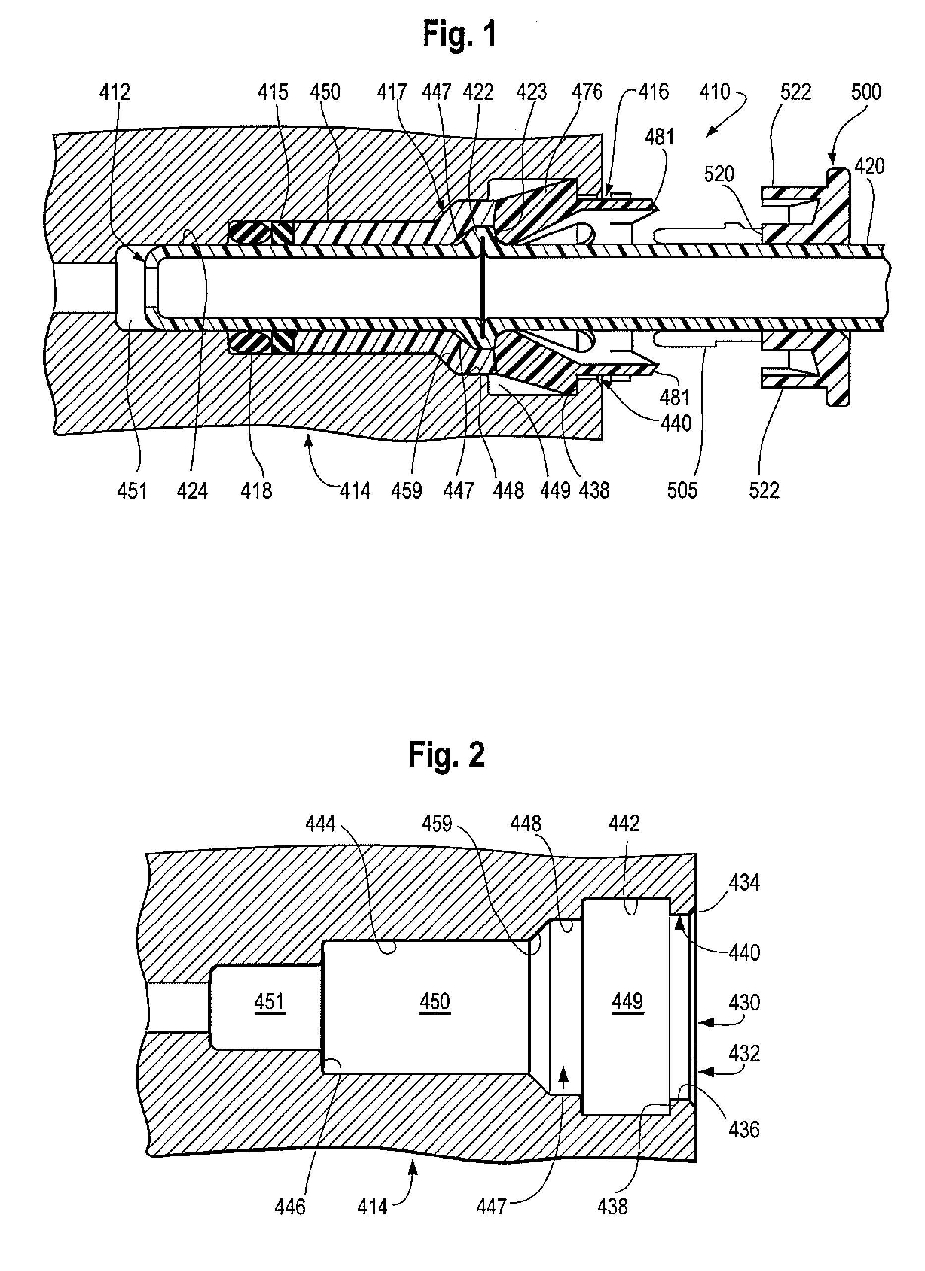
[0026]The fluid coupling assembly 410 of FIGS. 1-15 is a part of a fluid system. It joins a hollow tube 420 to a fluid system component 414 in fluid tight relation. The tube 420 defines a male member 412 which includes a radially directed annular upset 422 spaced from the free end of the tube. The male member includes an outer cylindrical sealing surface 424 between the tube end and the upset 422.

[0027]The coupling assembly includes a retainer 416, a sealing member 418, an inner spacer 415, and an outer spacer or cylinder 417. These components releasably secure the tube male member 412 to a body component 414 in a fluid tight relation.

[0028]The component body 414 to which the tube is attached is illustrated here as an “ABS unit” of an automotive brake system. However, the component could be a master cylinder, brake caliper, or other high or low pressure system component. It could also be any form of body defining a cavity or bore to receive the tube end and connection components.

[00...


PUM


Abstract

A quick connector coupling assembly includes a retainer to connect a rigid tube to a hollow body component. A sleeve extending between a fluid sealing member and the retainer includes a rearward abutment surface in abutting contact with the retainer. The retainer locking arms include forward abutment surfaces in abutting relation with the tube upset and forward abutment surfaces in abutting relation with the sleeve. An insertion verifier includes a ring portion with axially extending legs positioned in the slots between the retainer locking arms. At least one leg includes a releasable latch engaged with the retainer in the slots between the locking arms. Guide elements on the retainer and insertion verifier align the verifier legs and retainer slots on insertion of the verifier.

Description

RELATED APPLICATIONS[0001]This application claims priority under 35 USC 119 to provisional application No. 60 / 895,925 filed Mar. 20, 2007.BACKGROUND OF THE INVENTION[0002]This application relates to quick connector coupling assemblies for fluid systems, and more particularly to a quick connector for high pressure applications that releasably connects a male member formed at the end of a hollow tube to a hollow connector body.[0003]In the automotive and other fields, a quick connector coupling assembly is often utilized to provide a fluid connection between two components or conduits which generally include a male member, or tube, received and retained in a female connector body. Use of a quick connector is advantageous in that a sealed and secure fluid line may be established with minimum amount of time and expense.[0004]A retainer is often used to secure the male member within the connector body. One such type of retainer includes a plurality of locking members which extend between...

Claims


Application Information

Patent Timeline
Patent Type & Authority Applications(United States)
IPC IPC(8): F16L35/00
CPCF16L2201/10F16L37/0987F16L37/091F16L37/08
Inventor GUNDERSON, STEPHEN H.
Owner TI GRP AUTOMOTIVE SYST LLC
Learn More