
Establishment of message context in a collaboration system

Active Publication Date: 2008-09-18
ACCENTURE GLOBAL SERVICES LTD
View PDF88 Cites 48 Cited by
  • Summary
  • Abstract
  • Description
  • Claims
  • Application Information

AI Technical Summary

Benefits of technology

[0006]The present invention overcomes the limitations of the prior art described above through the use of an integrated collaboration system. The collaboration system in accordance with the present invention draws upon three guiding principles in its structure and operation. First, it is necessary to organize communication channels between collaboration team members. Second, it is necessary to build context around communications between team members. Third, wherever possible, relationships between collaborators should be enhanced. To this end, the collaboration system of the present invention provides various components that allow currently-used communication channels, e.g., electronic mail, instant messaging, etc., and content formats, e.g., text, audio, images, video, etc., to be organized such that contextual information surrounding messages sent within the system is more readily captured and used to organize the messages.
[0007]Thus, in one aspect of the inventive collaboration system, a processing device (e.g., a user terminal) used to support communications between users of the collaboration system is provided with a graphical user interface, i.e., a display and at least one user input device. A graphical context activation mechanism associated with a discussion between users of the collaboration system may be displayed. A selection input may be received in response to selection of the graphical context activation mechanism via the at least one user input device. Responsive to the selection input, a graphical illustration of information regarding the users participating in the discussion is displayed. In a presently preferred embodiment, the graphical illustration may comprise indicia of location of at least one of the users that may be displayed, for example, within the context of a geographical map. The graphical illustration may further comprise indicia of identity of at least one of the users, for example, visual depictions of such users. Additionally, a textual context activation mechanism may be provided and utilized in the same manner, thereby allowing text-based context regarding the message to be displayed such as at least a portion of the discussion, i.e., other messages. Individual discussions, each optionally comprising an urgency indicator, may be individually selected for further display. In this manner, team-wide context and participation may be more readily established, thereby fostering better understanding between team members and, consequently, more efficient collaboration.

Problems solved by technology

While such collaborative project teams typically enjoy the benefit of being able to draw upon efficient resources, the remoteness between team members can give rise to significant challenges that may significantly undercut, or entirely overwhelm, the efficiencies gained.
For example, where the project at hand comprises complex work involving a significant need for interaction between team members, remote collaborators that are not co-located with project management often have a difficult time establishing contextual knowledge relevant to the project.
For example, on a software development project, a developer in India may not fully appreciate the project requirements worked out through face-to-face meetings with the customer by U.S.-based project managers.
On the other hand, a project manager may not be able to quickly appreciate the subtleties of a technological issue encountered by the development team without significantly interacting with the developers.
Such inefficiencies can be compounded by the fact that different team members may have different levels of experience and knowledge, thereby making it difficult to maintain quality.
Additionally, differences in time zones between team members may create substantial lags in response time when critical issues arise, and provide a limited amount of time in which multiple team members may conference together.
Further still, differences in culture or language may create difficulties when trying to understand implied instructions from team management.
While such tools are individually suited for the particular tasks for which they are designed, collectively, they typically are unable to provide the necessary level of structure and support to maximize efficiency of the collaboration team.
Further, existing tools that may contain workflow functionality to formalize and structure standard types of communication, e.g., issue tracking, risk management, document versioning, do not account for informal communications that are necessary to perform collaborative work.
Stated another way, there currently are no systems or tools that provide coordinated operation between such separate collaboration tools.

Method used


Image

  • Establishment of message context in a collaboration system
  • Establishment of message context in a collaboration system
  • Establishment of message context in a collaboration system

Examples


Embodiment Construction

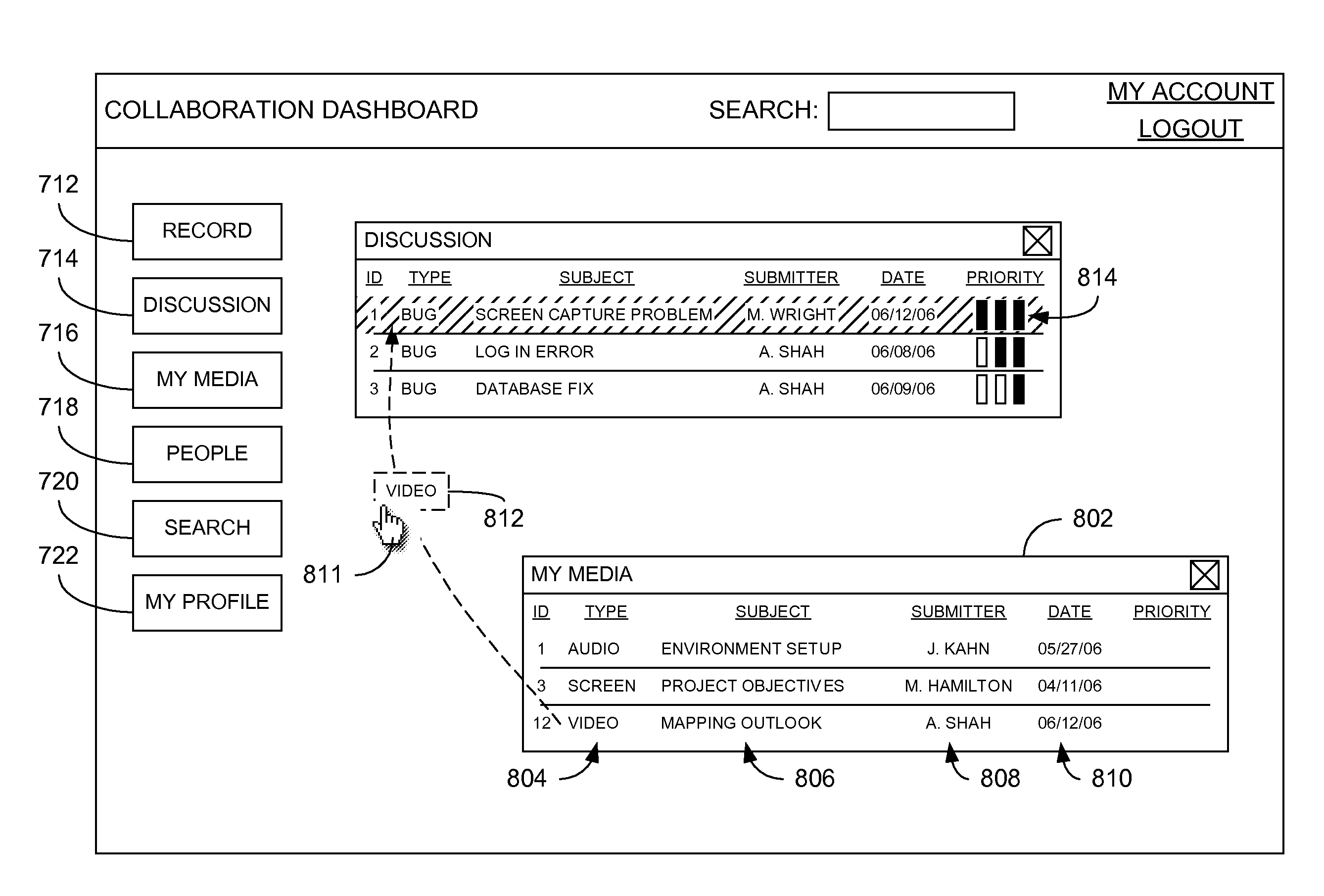
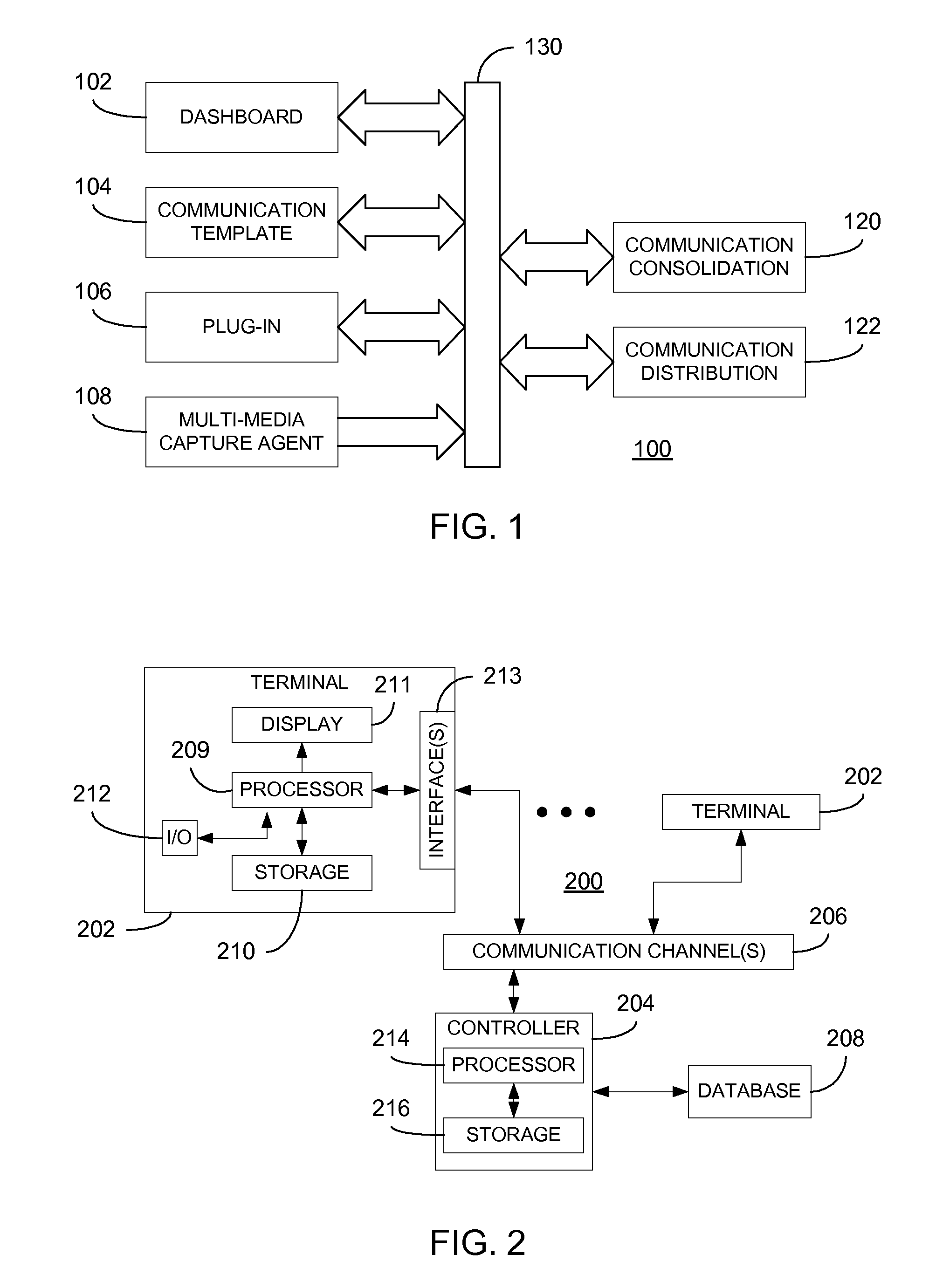
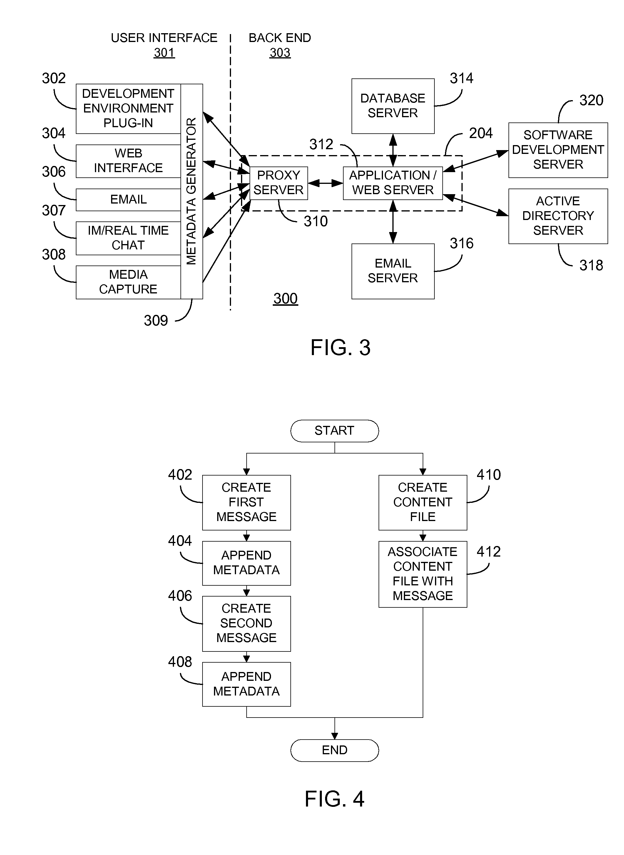
[0021]Referring now to FIG. 1, a collaboration system 100 in accordance with the present invention is functionally illustrated. The collaboration system 100 is essentially a communication system that is enhanced with features that provide greater support to collaborative teams than currently available. In particular, the system 100 comprises one or more user interface components 102-108 and one or more back-end components 120, 122 communicating with each other via at least one communication channel 130. In a presently preferred embodiment, each of the interface components 102-108 and each of the back-end components 120, 122 are implemented using known software programming techniques. Using such techniques, suitable processing devices (such as desktop / laptop / handheld computers, mobile communication devices such as cellular phones, personal digital assistants, one or more server computers, etc.) may operate under the control of executable instructions to carry out the various function...


PUM


Abstract

A processing device used to support communications between users of the collaboration system is provided with a graphical user interface. A graphical context activation mechanism associated with a discussion between users of the collaboration system may be displayed. Responsive to a selection input, a graphical illustration of information regarding the users participating in the discussion is displayed. The graphical illustration may comprise indicia of location of at least one of the users that may be displayed, for example, within the context of a geographical map. The graphical illustration may further comprise indicia of identity of at least one of the users. Additionally, a textual context activation mechanism may be provided and utilized in the same manner, thereby allowing text-based context regarding the message to be displayed. In this manner, team-wide context may be more readily established.

Description

CROSS-REFERENCE TO RELATED APPLICATIONS[0001]The present invention is related to co-pending applications having attorney docket numbers 33836.00.0119 and 33836.00.0140, filed on even date herewith.FIELD OF THE INVENTION[0002]The present invention relates to techniques for fostering a collaborative environment and, in particular, to a collaboration system that provides improved capture, distribution and maintenance of communications and contexts therefore.BACKGROUND OF THE INVENTION[0003]With the advent of more powerful communication technologies, the use of cross-border collaborative project teams has increased. For example, it is not uncommon in the software development industry to have teams of developers and management spread across the globe. While such collaborative project teams typically enjoy the benefit of being able to draw upon efficient resources, the remoteness between team members can give rise to significant challenges that may significantly undercut, or entirely over...

Claims


Application Information

Patent Timeline
IPC IPC(8): G06F3/00
CPCG06Q10/10
Inventor HAMILTON, MARYKORYTKOWSKI, BEATAKAHN, JOSHUANEBOLSKY, CHARLES
Owner ACCENTURE GLOBAL SERVICES LTD
Learn More