Image display device

Active Publication Date: 2008-09-18
SAMSUNG DISPLAY CO LTD +1
View PDF10 Cites 68 Cited by
  • Summary
  • Abstract
  • Description
  • Claims
  • Application Information

AI Technical Summary

Benefits of technology

[0010]According to the invention, the self-luminous display device having the input function such as a touch panel can be provided by detecting a temperature characteristic of the self-luminous element, while the degradation of aperture ratio, increase of power consumption, and degradation of life are restrained without adding a newly sensed device in the display area of display device.

Problems solved by technology

However, there arises a problem such as degradation for a display quality, for example, a luminescence etc., and cost increase, since the touch panel is laminated on the surface of display device.

Method used


Image

  • Image display device
  • Image display device
  • Image display device

Examples


first embodiment

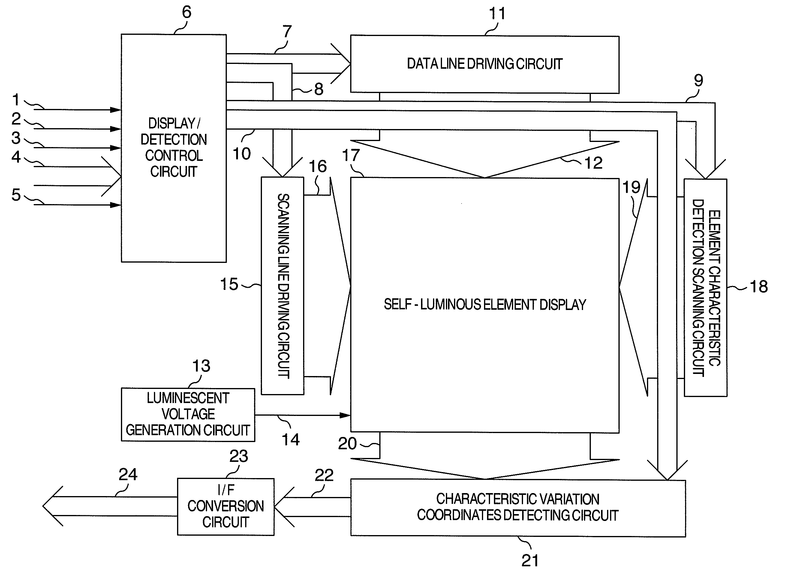
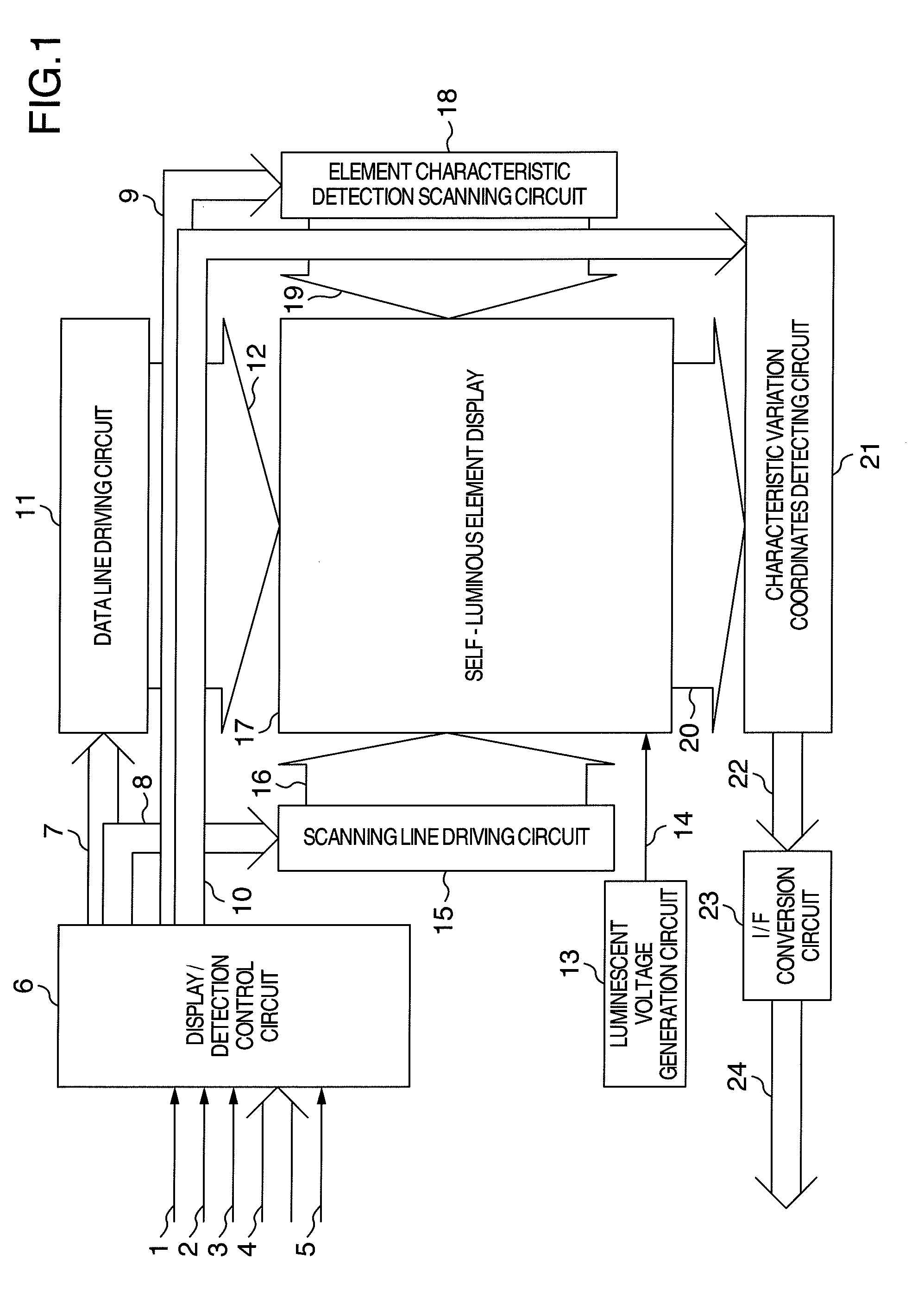
[0027]FIG. 1 shows an example of a self-luminous element display device in the first embodiment of the invention. Referring to FIG. 1, a reference numeral 1 denotes a horizontal sync signal; 2, a vertical sync signal; 3, a data enable signal; 4, display data; and 5, a sync clock. The horizontal sync signal 1 is a signal of one-screen period (one frame period) of a display. The vertical sync signal 2 is a signal of one-horizontal period. The data enable signal 3 is a signal indicating a time period (display effective time period) during which the display data 4 is effective. All of the foregoing signals are inputted in synchronization with the sync clock 5. In the case of this embodiment, a description will be concerned with the following assumption such that one-screen amount of the display data 4 is, in turn, transferred from a left-top end pixel on a screen by a raster scan method, and information of one pixel is constituted by 6-bit digital data. A reference numeral 6 denotes a d...

second embodiment

[0047]Hereinafter, a second embodiment in the invention will be described with reference to FIGS. 12, 13 and 14.

[0048]FIG. 12 shows an example of a self-luminous element display device of the second embodiment in the invention. Referring to FIG. 12, components with the same reference numerals in FIG. 1 correspond to the first embodiment, and are operated as described in the first embodiment. A reference numeral 142 denotes a display / detection change-over control circuit; 143, a display / detection change-over control signal; 144, a data line driving / characteristic variation coordinates detecting circuit; 145, a data line driving / detection line outputting signal; and 146, a data line / detection line common self-luminous element display. The display / detection change-over control circuit 142 generates the data line control signal 7, scanning line control signal 8 and detection scanning line control signal 9, as a conventional manner. The display / detection change-over control circuit 142 a...


PUM


Abstract

An image display device includes switches directly connected a constant current source to a self-luminous element to be able to detect a characteristic of the self-luminous element, generate a coordinates and convert information of the characteristic and coordinates into a system communication signal, transferring an input with a temperature variation to a system side.

Description

CLAIM OF PRIORITY[0001]The present application claims priority from Japanese Application No. 2007-067807 filed on Mar. 16, 2007, the content of which is hereby incorporated by reference into this application.BACKGROUND OF THE INVENTION[0002]The present invention relates to an image display device having self-luminous elements thereon, such as EL (Electroluminescence) elements, organic EL elements, etc., and a driving method of the same.[0003]The self-luminous element typified by the EL element, organic EL element, etc. has a property such that a luminance of the element is proportional to a current amount flown into the self-luminous element. Therefore, a gradation display can be realized by controlling the current amount flown into the element. A plurality of self-luminous elements as described above are arranged, so that a display device can be realized.[0004]On the other hand, a touch panel has been used as a technique for applying an input function to a display device. However, ...

Claims


Application Information

Patent Timeline
IPC IPC(8): G09G3/30
CPCG06F3/0412G09G3/3225G09G3/3233G09G3/3275G09G2320/041G09G2300/0465G09G2300/0842G09G2320/029G09G2320/0295G09G5/18
Inventor KASAI, NARUHIKOISHII, MASATOMIYAMOTO, MITSUHIDEKOHNO, TOHRUAKIMOTO, HAJIME
Owner SAMSUNG DISPLAY CO LTD
Why Eureka
Try Eureka