
Electrical Door Latch

a technology of electric door latches and latches, which is applied in the direction of emergency situation locks, fastening means, power transmission/actuation features, etc., can solve the problems of actuators not having enough force for operation and increasing the force to release doors

Inactive Publication Date: 2008-09-18
INTIER AUTOMOTIVE CLOSURES SPA CASCINE VIA
View PDF31 Cites 140 Cited by
  • Summary
  • Abstract
  • Description
  • Claims
  • Application Information

AI Technical Summary

Benefits of technology

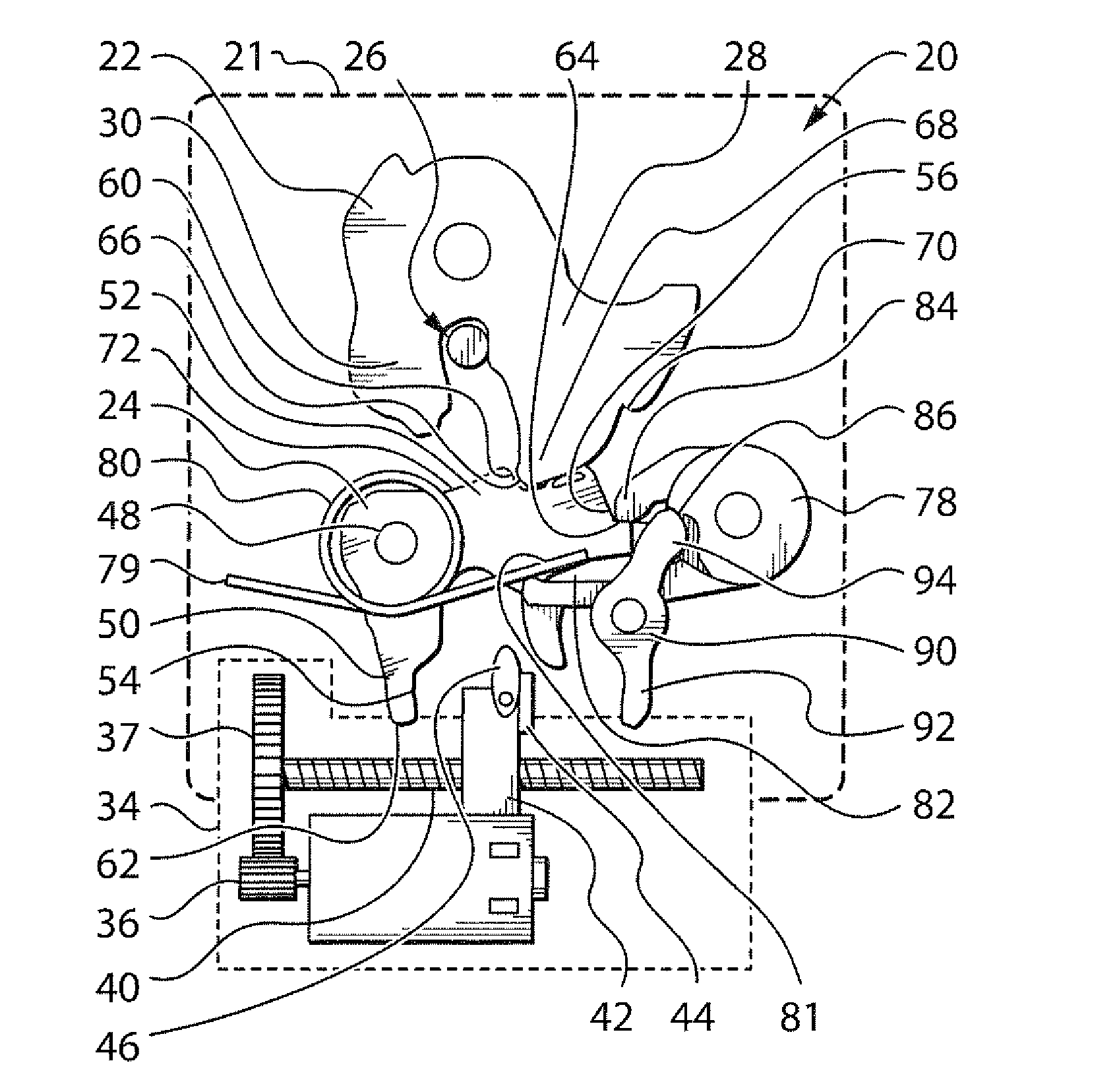
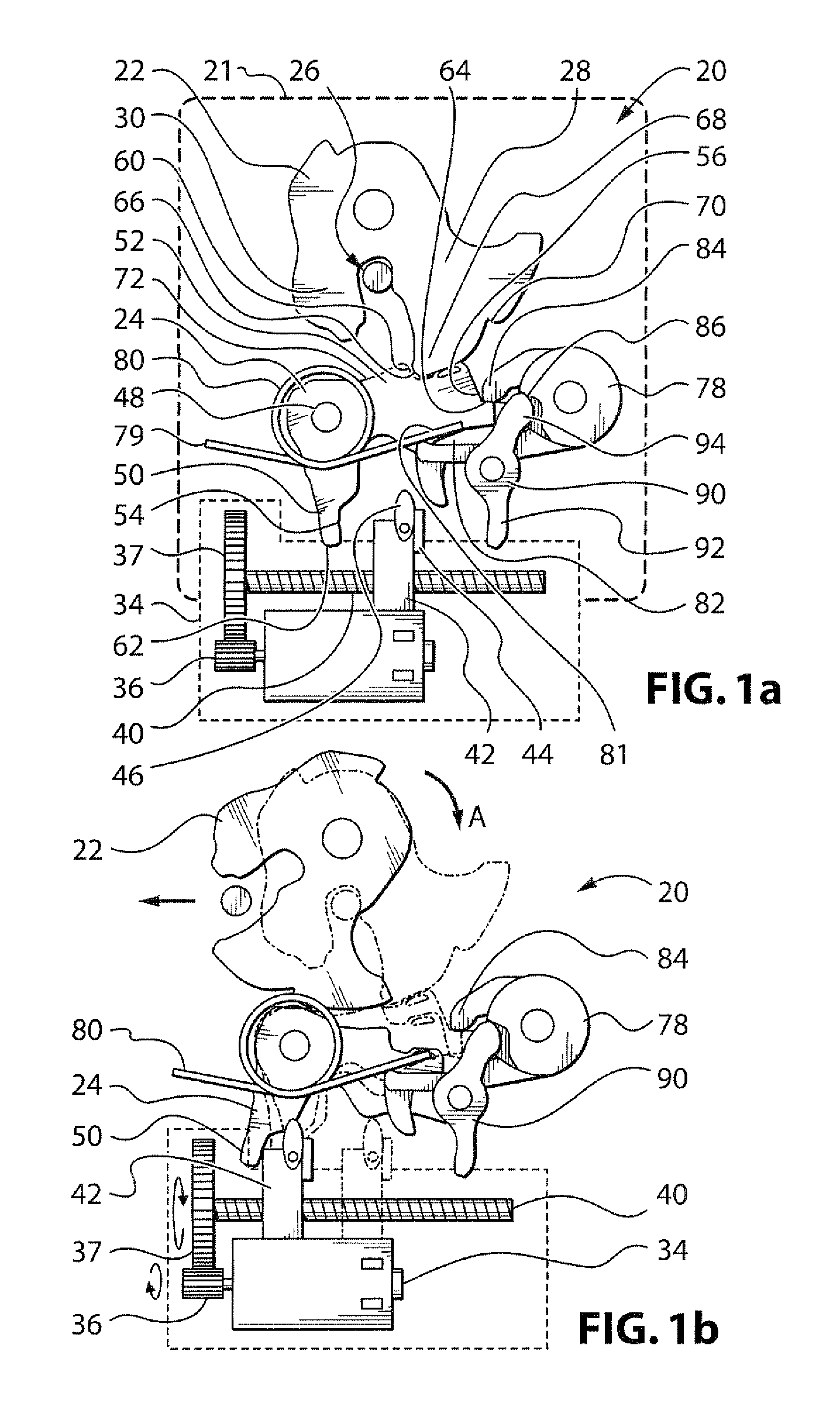
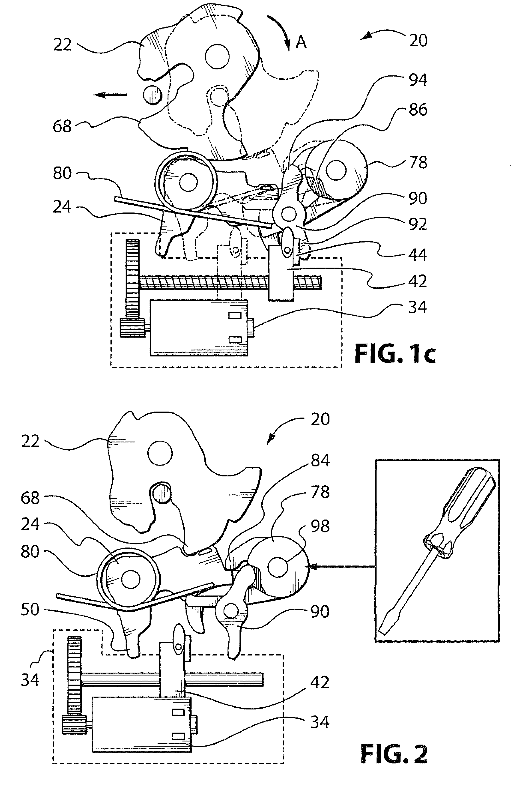
[0005]In an aspect of the the invention there is a door latch apparatus. It has a ratchet, a co-operating pawl, a primary pawl release, a secondary pawl release, and an actuator. The ratchet is movable between an open position in which a mating striker can be engaged and disengaged therefrom, and a closed position in which the mating striker is captured thereby. The pawl is movable between a first position preventing movement of the ratchet from the closed position to the open position, and a second position permitting movement of the ratchet from the closed position to the open position, whereby to permit release of the striker. The actuator is connected in a first path to cause the primary pawl release to urge the pawl to the second position. The actuator is connected in a second path to cause the secondary pawl release to urge the pawl to the second position. The actuator is operable to transmit a release signal along the second path in the event that the pawl is not released when a release signal is transmitted along the first drive path.

Problems solved by technology

In case of a crash, the force to release the door could increase and the actuator may not have enough force for the operation.

Method used


Image

  • Electrical Door Latch
  • Electrical Door Latch
  • Electrical Door Latch

Examples


Embodiment Construction

[0067]The description that follows, and the embodiments described therein, are provided by way of illustration of an example, or examples, of particular embodiments of the principles, aspects or features of the present invention. These examples are provided for the purposes of explanation, and not of limitation, of those principles and of the invention. In the description, like parts are marked throughout the specification and the drawings with the same respective reference numerals. The drawings are generally to scale unless noted otherwise, although the scale may differ from drawing to drawing. Reference to directions such as up and down, front and back, left and right, top and bottom, may tend to be arbitrary, and these terms may be used for convenience rather than defining a required orientation, unless noted otherwise. The terminology used in this specification is thought to be consistent with the customary and ordinary meanings of those terms as they would be understood by a p...


PUM


Abstract

A latching apparatus may have a normal mode of operation in which a mechanical signal is employed to actuate a door pawl, and hence to release a door latch ratchet. An electrical actuator may be employed to send that mechanical signal, and operation of the actuator may be governed by an electronic control unit (ECU). The latch apparatus may also have a second, or emergency, mode of operation in which a second mechanical signal path is employed either to cause an augmented force to be employed to release the pawl, or to cause a sudden impulse to urge the pawl to release, the sudden impulse being driven by a release of energy from an energy storage device, in particular a mechanical energy storage device. The apparatus may include either an electrical or a mechanical door handle interrupt to prevent unwanted activation. The device may also include an auxiliary electrical back-up power source in the event of a main power source failure.

Description

[0001]This application claim the benefits of U.S. Provisional Application No. 60 / 890,066, filed Feb. 15, 2007.FIELD OF THE INVENTION[0002]The present application relates to the filed of door latches, and, in particular, of door latches such as may be employed in automotive apparatus.BACKGROUND OF THE INVENTION[0003]One of the defining characteristics of an electrical door latch (E-latch) is that it does not have a mechanical linkage to an outside or inside door handle. Instead, the door is released by an actuator, in response to an electrical signal coming from the handles. In case of a crash, the force to release the door could increase and the actuator may not have enough force for the operation.[0004]It therefore desired to provide a mechanical storage force able to release the latch when reaction forces on the ratchet increases (for example after crash). In such a solution, it would also be useful to enable the release actuator to release the latch with conventional lower forces...

Claims


Application Information

Patent Timeline
Patent Type & Authority Applications(United States)
IPC IPC(8): E05C3/16
CPCE05B77/02E05B81/40E05B81/14Y10T292/1047Y10T292/1082
Inventor CUMBO, FRANCESCOTAURASI, MARCOOTTINO, FRANCO GIOVANNIMARLIA, MARCO
Owner INTIER AUTOMOTIVE CLOSURES SPA CASCINE VIA
Learn More