
Virtual machine configuration system and method thereof

a virtual machine and configuration system technology, applied in the field of virtual machine configuration system and a method thereof, can solve the problems of difficult to ensure service continuity, impossible normal operation, and delay in transfer of these methods

Active Publication Date: 2008-09-11
NEC CORP
View PDF11 Cites 176 Cited by
  • Summary
  • Abstract
  • Description
  • Claims
  • Application Information

AI Technical Summary

Benefits of technology

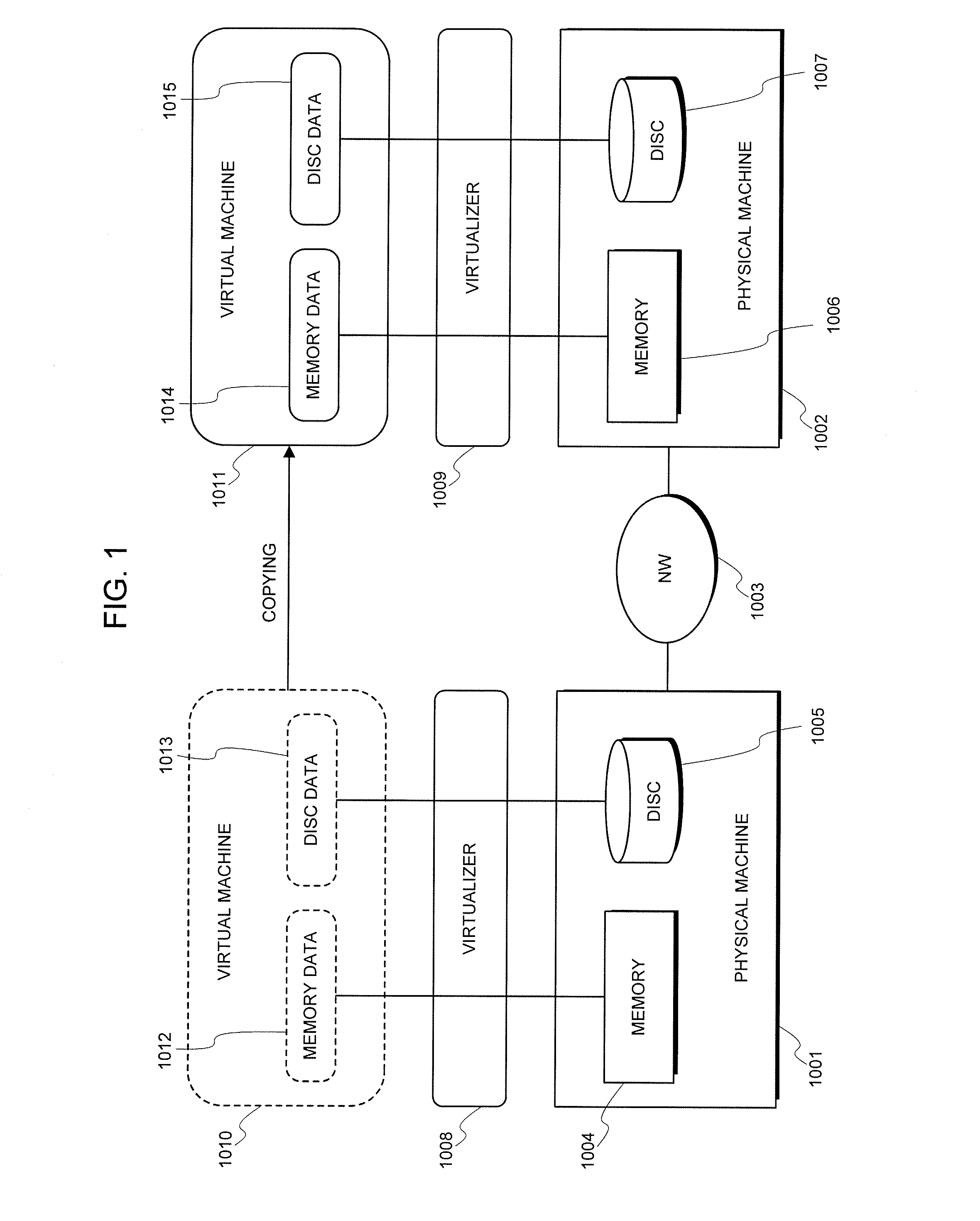
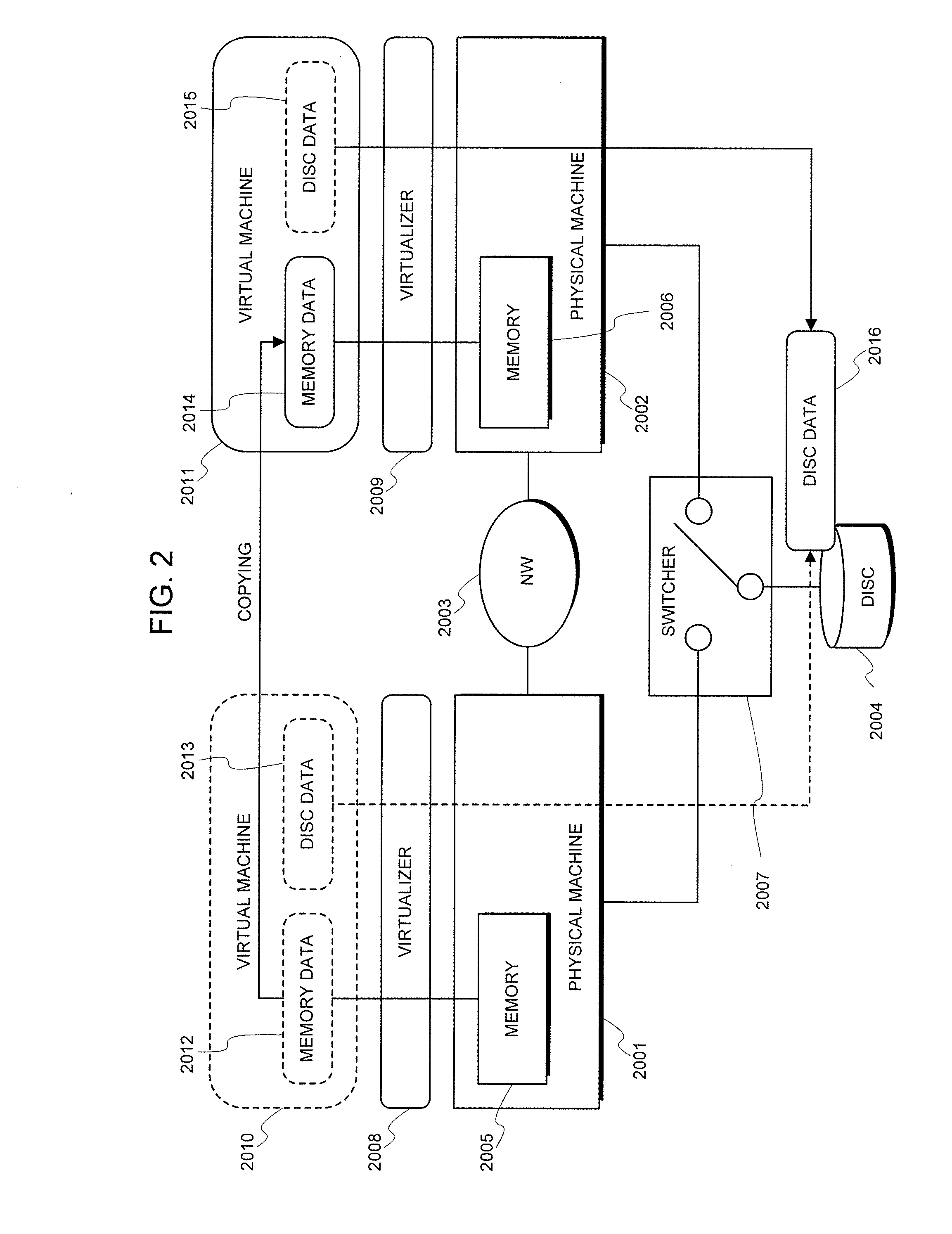
[0066]The effect of the present invention lies in a point of making it possible to provide a service continuity, of which the level is identical to that of the system presuming that the disc-sharing system being typified by SAN etc. is utilized, only with the conventional migration of the disc device at the moment of migrating the virtual machine to a different physical machine in a visualization environment.
[0067]The reason is that the present invention makes it possible to make a configuration so that by performing a migration operation of the disc device between the physical machines in a background independent of the service that is provided by the virtual machine, a time necessary for its migration does not exert an influence over a continuity of the service.

Problems solved by technology

The reason is that in a case where the disc access has occurred due to an access by a software process on the VM to the data, absence of the physical disc, being an entity, causes an error to be generated, and resultantly, makes the normal operation impossible.
However, a transfer delay occurs in these methods, which premise that the disc data is shared via the network.
The reason lies in a point that, in the related art 1, a service continuity is difficult to secure when seen from a user's standpoint because the physical resource is caused to correspond to the virtual resource after making a re-configuration in the physical resources, for example, after manually deleting / installing the physical device.
This necessitates the expensive dedicated device such as the SAN, and the visualization with the software such as the nfs causes the overhead of the protocol processing to hang.

Method used


Image

  • Virtual machine configuration system and method thereof
  • Virtual machine configuration system and method thereof
  • Virtual machine configuration system and method thereof

Examples


example

[0095]Hereinafter, an exemplary example of the present invention will be explained in details by employing the accompanied drawings.

[0096](Disc Redundancy)

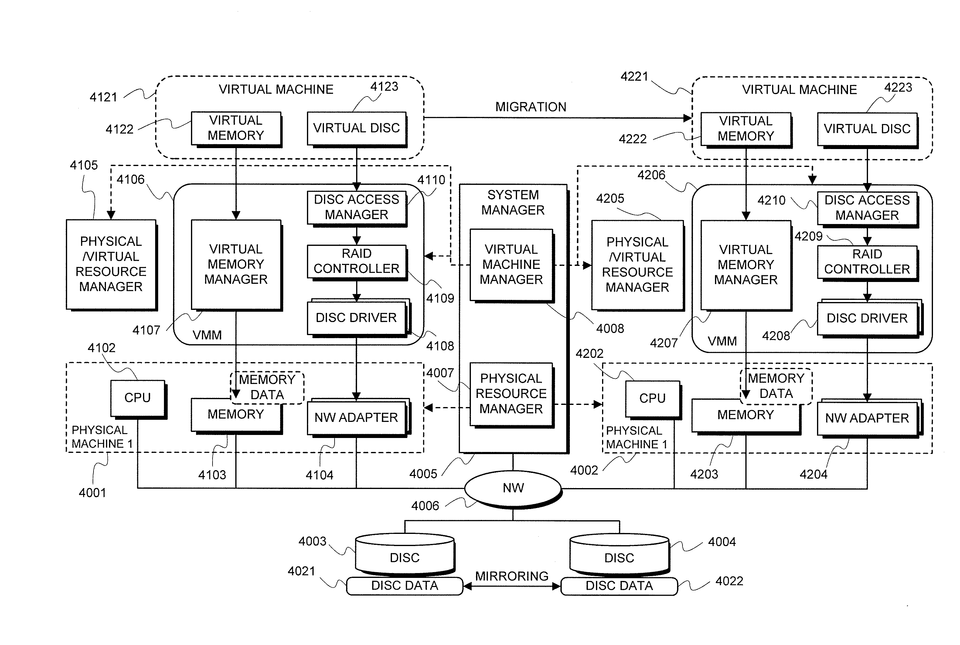
[0097]According to FIG. 4, as a first embodiment of the present invention, the system is provided that is configured of physical machines 4001 and 4002 each of which is connected with the other via a MW circuit 4006 and is capable of making data communication, discs 4003 and 4004 each of which is connected to the physical machine 4001 or the physical machine 4002, and a system manager 4005.

[0098]Herein, each of the discs 4003 and 4004, which is a non-volatile memory device that is representatively typified by a hard disc, is not limited hereto.

[0099]The physical machines 4001 and 4002 are configured of CPUs 4102 and 4202, memories 4103 and 4203, and network adapters 4104 and 4204, respectively.

[0100]Each of the memories 4103 and 4203, which is a non-volatile memory device that is typified by a RAM (Random Access Memory), is not li...


PUM


Abstract

A virtual machine configuration system, comprising a virtualizer for, in a virtualization environment in which a plurality of physical resources connected mutually through a network circuit has been arranged on a computer system sectioned into a plurality of partitions, dynamically changing a physical resource configuration and a virtual machine configuration while simultaneously controlling a configuration of the physical resources of the partition and a configuration of virtual resources allotted to virtual machines without exerting an influence over an application service operating on the virtual machine.

Description

INCORPORATION BY REFERENCE[0001]This application is based upon and claims the benefit of priority from Japanese patent application No. 2007-058608, filed on Mar. 8, 2007, the disclosure of which is incorporated herein in its entirety by reference.RELATED ART[0002]The present invention relates to a virtual machine configuration system and a method thereof, and more particularly to a virtual machine configuration system and a method thereof that make it possible to provide a virtualization environment having a plurality of computer machines in which resources are efficiently utilized.[0003]As one example of a computer system or a network system in recent years, there exists the system into which a configuration, which enables a plurality of operating systems (OS) to concurrently operate on an identical physical server by introducing a virtualizer called a Virtual Machine Monitor (VMM), has been introduced. Each OS is installed onto a physical server, and likewise, the OS is installed ...

Claims


Application Information

Patent Timeline
IPC IPC(8): G06F9/455
CPCG06F9/45558G06F9/5077G06F2009/4557G06F3/0689G06F9/4856
Inventor KAMI, NOBUHARU
Owner NEC CORP
Learn More