
In-system programming system and method for motherboard

a motherboard and programming system technology, applied in the field of server motherboard programming system, can solve the problems of difficult configuration or programming, inability to program, and difficulty in motherboard wiring, so as to ensure the safety and stability of the motherboard, and simple and convenient motherboard programming.

Inactive Publication Date: 2008-09-11
INVENTEC CORP
View PDF4 Cites 8 Cited by
  • Summary
  • Abstract
  • Description
  • Claims
  • Application Information

AI Technical Summary

Benefits of technology

[0007]In order to solve the problems and defects in the aforementioned prior art, the present invention is directed to an in-system programming system and method for a motherboard, which not only achieves the simple and convenient programming of the motherboard, but also ensures the safety and stability of the motherboard.
[0012]In the present invention, through disposing the on-board programmer on the motherboard, i.e., the motherboard is connected to the on-board programmer through wiring when being designed, the type, quantity, and bus interface of the chips to be burned are determined. Then, a programming interface is provided for the chips to be programmed through the on-board programmer, thereby avoiding the problem that the distance between the on-board programmer and the buses of the devices on the motherboard is excessively long, and thus reducing the unstable factors of the buses caused by the distance of the buses, and thus achieving the in-system programming of the chip with more pins.
[0013]Furthermore, through the aforementioned configuration, programming staff and users cannot face the reserved programming pins directly, which thus protects the contents in the devices on the motherboard and enhances the safety and stability of the motherboard.
[0014]The present invention controls the in-system programming of the chips to be programmed through connecting the programmer to the programming interface connector, and utilizing the communication between an original universal serial bus (USB) interface on the motherboard and a computer programming software. Therefore, with regard to a movably-connected programmer, the programmer can be used repeatedly, thereby reducing the manufacturing cost.

Problems solved by technology

The bus interfaces of the devices are quite different in types and they are difficult to be configured or programmed.
However, the in-system programming method in the prior art still has the following defects.
If the chip is a flash with a parallel interface, a lot of pin headers are required to be exposed outside, which thus causing a difficult in the wiring of the motherboard, so that the in-system programming is not suitable for the current flash.
The reserved pins become useless once the server leaves the factory, which not only wastes the space of the motherboard, but also enables a user to change the contents of the chip of the motherboard, and if the contents of the chip can be read and modified through the reserved pins, the motherboard is unstable.
The programmer is far away from a target programmable chip, which increases the distance for signal transmission, thereby affecting signal intensity and accuracy of the transmission.
Especially, the increasing of the circuit length causes signal crosstalk, which thus degrades the anti-interference capability of a signal.
Furthermore, an introduced in-system resistor degrades the stability of the signal, which greatly influences the accuracy of the burned result.
The chips to be programmed are distributed on the motherboard in a scattered manner, and in the course of programming, the circuits of the programmer are respectively connected to corresponding target chips depending upon functions, so the efficiency is low and mistakes often occur, and thereby missing contents.
The programmer cannot be applicable for all the chips to be programmed on the motherboard, and more programming tools are required to program the chips, so the operation is complicated and time-consuming.

Method used


Image

  • In-system programming system and method for motherboard
  • In-system programming system and method for motherboard
  • In-system programming system and method for motherboard

Examples


Embodiment Construction

[0020]The features and practice of the preferred embodiments of the present invention will be illustrated below in detail with reference to the drawings.

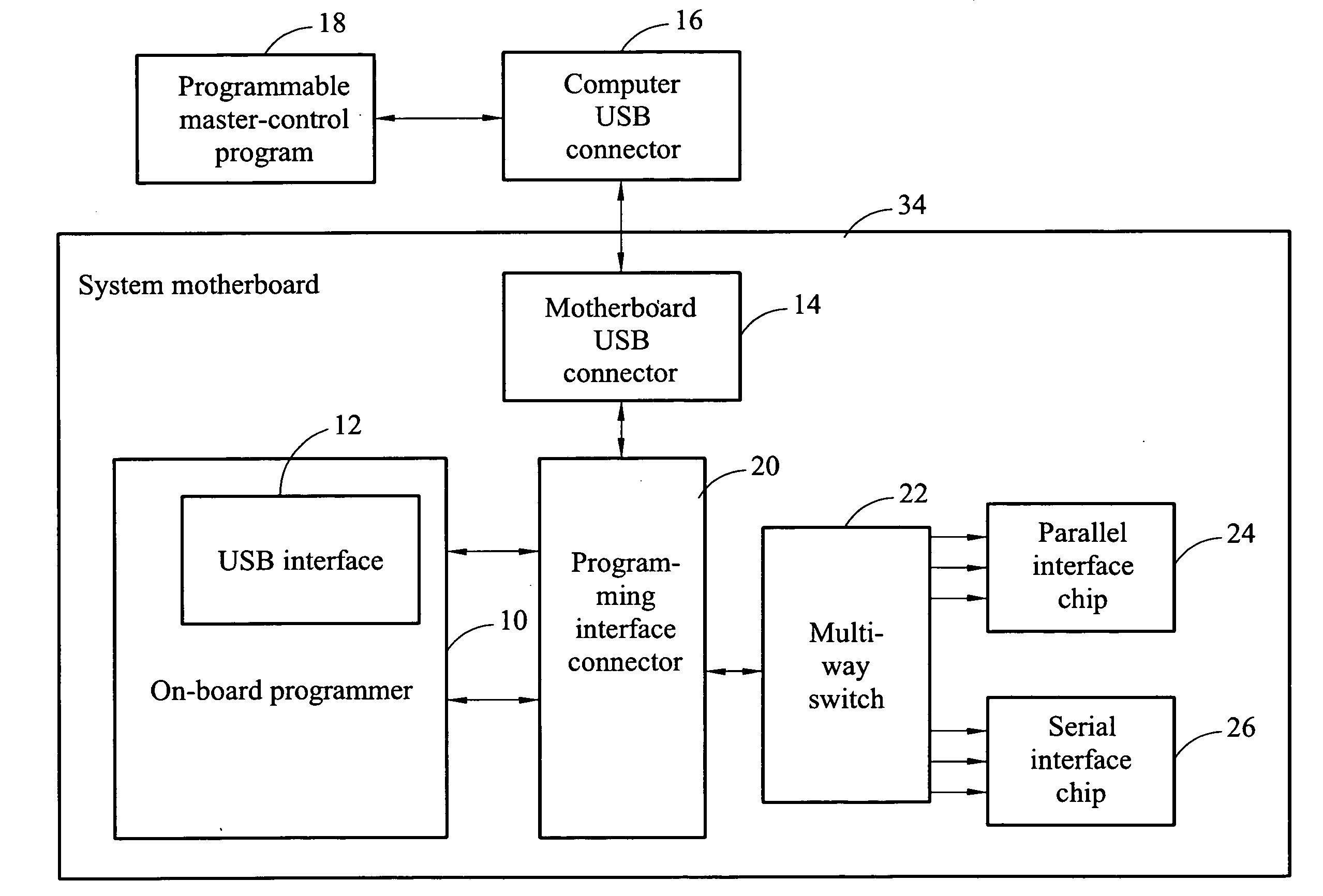
[0021]Referring to FIG. 1, it is a block diagram of an in-system programming system for a motherboard according to the present invention.

[0022]As shown in FIG. 1, the in-system programming system for a motherboard includes a programming interface connector 20 disposed on a system motherboard 34. Reserved programming pins are directly connected to the programming interface connector 20, and exposed outside the programming interface connector 20. One end of the programming interface connector 20 is connected to a plurality of chips to be programmed through pins hidden in the system motherboard 34, such as an electrically erasable programmable read-only memory (EEPROM), a flash, and a peripheral interface controller (PIC). Furthermore, the other end of the programming interface connector 20 is connected to an on-board programmer 10 thr...


PUM


Abstract

An in-system programming system and method is provided, which is applicable for chip programming of a computer motherboard. Firstly, a programming interface is configured in the computer motherboard, in which one end of the programming interface is connected to an on-board programmer, and the other end is connected to a plurality of chips to be programmed, thereby achieving the communication between the on-board programmer and the chips. Next, a motherboard connector and the programming interface are connected, and the motherboard connector and the on-board programmer are communicated through a communication interface of the on-board programmer. Then, the other end of the motherboard connector is connected to a programmable master-control program. Then, when the programmable master-control program is used for programming, programming contents of the programmable master-control program are transmitted to the on-board programmer through the communication between the motherboard connector and the on-board programmer, so as to program the chip.

Description

BACKGROUND OF THE INVENTION[0001]1. Field of Invention[0002]The present invention relates to a programming system of a server motherboard, and more particularly to an in-system programming system of a motherboard and an implementation method therefor.[0003]2. Related Art[0004]Generally, many devices on a server motherboard are required to be correspondingly configured or programmed before leaving factories. The devices are mainly classified into storage units and controllers, in which the storage unit includes, for example, an electrically erasable programmable read-only memory (EEPROM), a flash, and the like, and the controller includes, for example, a peripheral interface controller (PIC) single-chip computer, a system on programmable chip (SOPC) single-chip computer, and the like. The bus interfaces of the devices are quite different in types and they are difficult to be configured or programmed.[0005]There are two schemes for programming the devices on the motherboard. One schem...

Claims


Application Information

Patent Timeline
IPC IPC(8): G06F9/00
CPCG06F13/10
Inventor JIANG, XIAOZHENG, QUAN-JIECHEN, TOMLIU, WIN-HARN
Owner INVENTEC CORP
Learn More