
Control and monitor signal transmission system

a technology of signal transmission system and control panel, which is applied in the direction of program control, electric programme control, instruments, etc., can solve the problems of lowering data reliability, inability to operate, and considerable drop in the output voltage of the power supply

Inactive Publication Date: 2008-09-11
ANYWIRE
View PDF10 Cites 8 Cited by
  • Summary
  • Abstract
  • Description
  • Claims
  • Application Information

AI Technical Summary

Benefits of technology

[0015]The present invention is provided to address the above-described problems in conventional configurations. A feature of the present invention is that it provides a highly reliable control and monitor signal transmission system by reducing possibility of malfunctions of the control and monitor signal transmission system due to a drop of power supply voltage or external noise.
[0022]One of the features of the present invention is that it may enable a control and monitor signal transmission system, wherein transmission and reception of a signal is performed by detecting a current during a pulse period of a transmission signal that is transmitted via a common transmission line, thereby improving a noise resistance characteristic so as to stably perform control communication, while the number of wires is minimized.
[0023]Another feature of the present invention is that it may require only a rising edge or a falling edge of pulse to be set for a signal-handling base point, and enables noise-resistance signal processing, while allowing the control and monitor signal transmission system to be achieved with a minimum number of wires.
[0024]Moreover, a circuit configuration of the present invention allows a noise limit relative to power supply voltage to be doubled.
[0032]As described above, the present invention enables the control and monitor signal transmission system, wherein stable signal transmission is achieved without having problems such as unstable signal level due to fluctuation or a drop of power supply voltage, a malfunction due to a drop of the signal level associated with extension of a data signal transmission line, or a malfunction due to noise that is generated on a transmission path or in the equipment being used.

Problems solved by technology

However, when power supply voltage drops, problems occur such as that a signal level also proportionally drops or that threshold voltage is not sufficiently obtained, causing unstable operation and lowering data reliability.
For example, when a battery-operated power supply is used, ambient temperature in a usage environment could affect an electromotive force of the batteries, leading to a considerable drop of output voltage of the power supply.
In other words, low ambient temperature decreases battery power output, causing a considerable drop of voltage due to load.
Accordingly, it is difficult to maintain a signal level in communication control that uses such a power supply, and a malfunction could occur.
Further, extension of a data signal transmission line is rigidly limited because problems are easily caused, such as a drop of a signal level due to the extension of the data signal transmission line or picking up of noise that is coupled into the data signal transmission line.
Meanwhile, there are unavoidable situations in a practical setting, such as that control from a remote location is required in factory premises, that each equipment is scattered throughout remote locations, or that equipment that could interfere with signals is placed in a signal path.

Method used


Image

  • Control and monitor signal transmission system
  • Control and monitor signal transmission system
  • Control and monitor signal transmission system

Examples


first embodiment

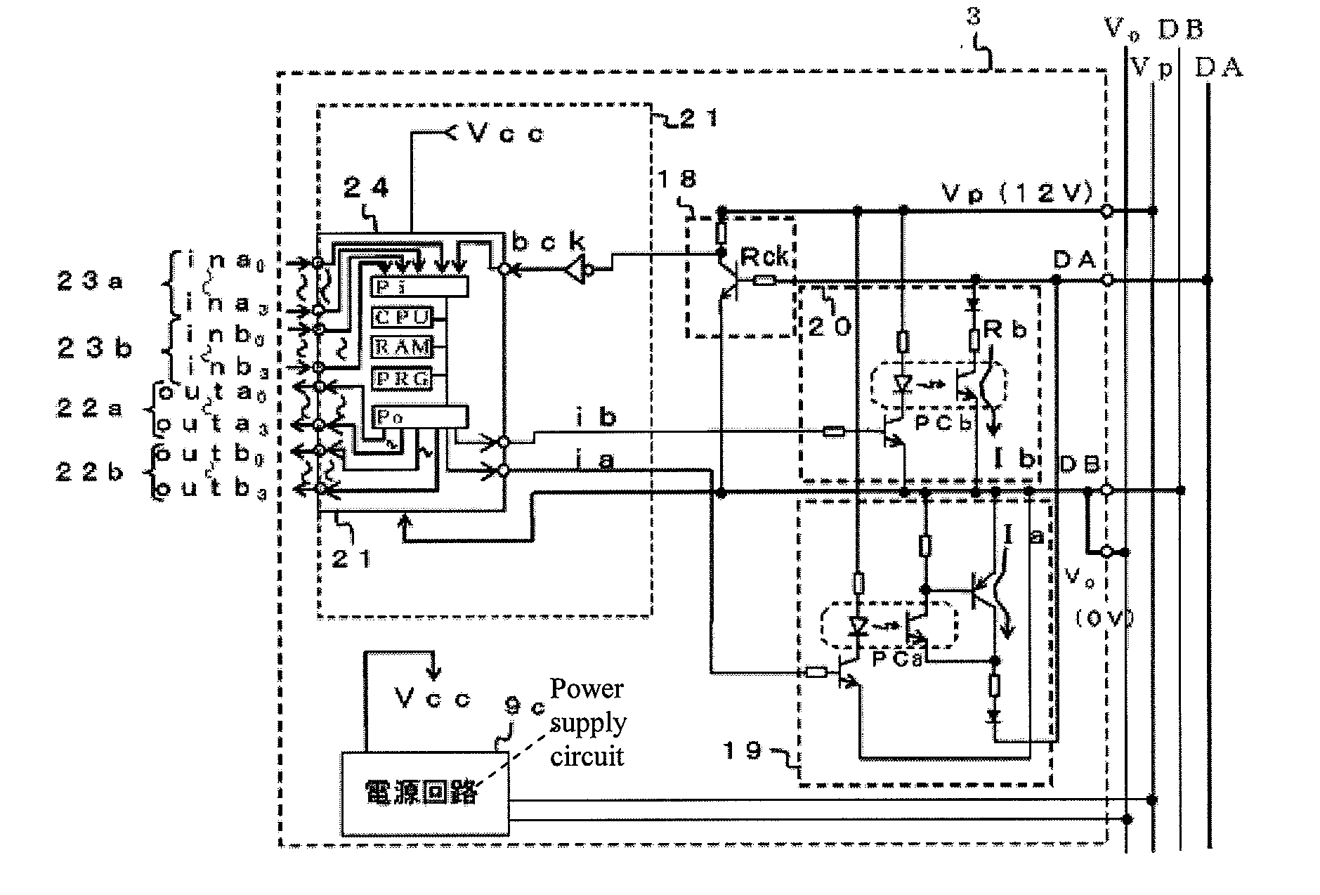
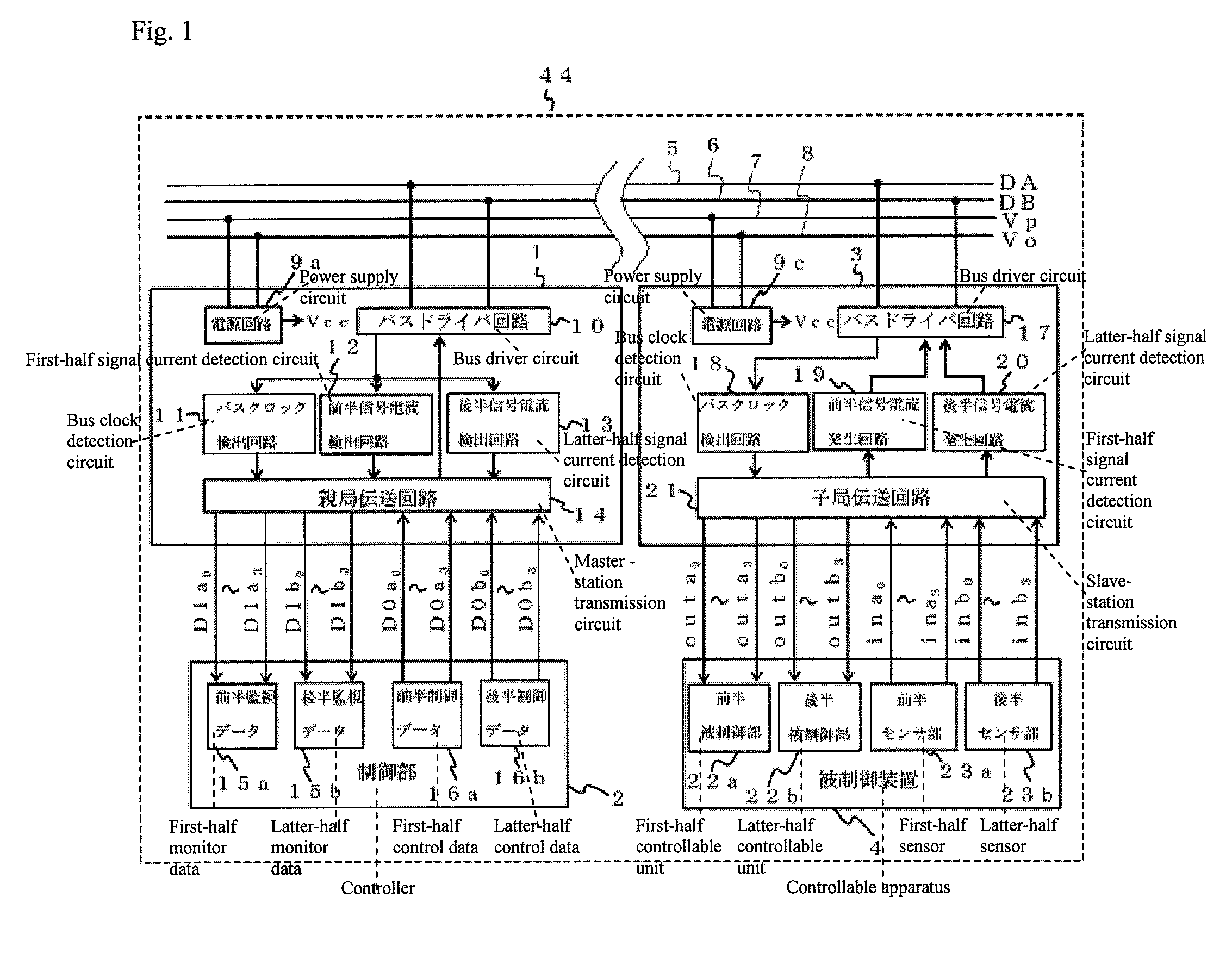
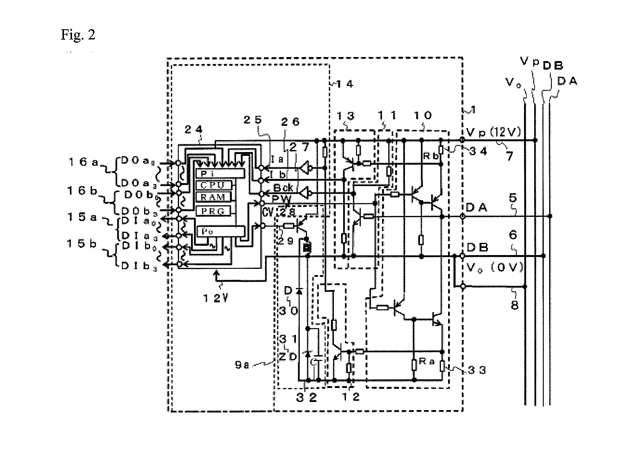
[0043]the present invention is explained with reference to FIGS. 1 to 5. FIG. 1 is an overall configuration of a control and monitor signal transmission system 44 of the present invention. In this embodiment, one slave station 3 is connected to single master station 1. However, a plurality of slave stations 3 are connected in a practical setting. FIG. 2 is a detailed internal configuration of master station 1 shown in FIG. 1. FIG. 3 is a signal transmission diagram that is shown in a time chart format of a signal used inside master station 1. FIG. 4 is a detailed internal configuration of slave station 3 shown in FIG. 1. FIG. 5 is a signal transmission diagram that is shown in a time chart format of a signal used inside slave station 3.

[0044]FIGS. 1 to 5 illustrate the first embodiment in detail. Specifically, FIG. 1 illustrates an example in which voltage of power supply line Vp and power supply line Vo is 12 V, and a potential of data signal transmission line DB6 is a neutral elec...

second embodiment

[0093]FIG. 6 shows an embodiment in which master station 1 uses voltage division. Specifically, FIG. 6 is a basic schematic diagram of a second embodiment showing a circuit diagram of the master station, illustrating a function block, in particular, of a microcomputer that is a master-station transmission circuit included in the master station.

[0094]FIG. 6 shows a detailed internal configuration of master station 1 of the second embodiment. Specifically, the voltage of power supply lines Vp 7 and Vo 8 is both 24V while the voltage of power supply lines Vp and Vo is both 12V in FIG. 1. An example in FIG. 6 shows in which power supply circuit 9b of master station 1 divides power supply lines Vp 7 and Vo 8, so as to allow data signal transmission line DB6 to be a neutral electric potential at 12V. The configuration except master station 1 is the same as the configuration shown in FIGS. 1 to 5.

[0095]Master station 1 is data-connected to slave station 3 through data signal transmission l...


PUM


Abstract

A master station has a master-station transmission circuit that extracts a serial monitor signal so as to convert a control data signal into monitor data by changing a duty ratio of negative and positive voltage-level periods, converting the control signal into a serial pulsing voltage signal, transmitting a monitor data signal that is superimposed on the serial pulsing voltage signal, and detecting the presence or absence of a signal of a current that flows during the negative and positive voltage-level periods. A plurality of slave stations respectively have a slave-station transmission circuit that identifies a duty ratio of the positive and negative voltage-level periods relative to each serial pulsing voltage signal, that extracts a control data signal so as to output the data to a controllable unit of the slave station.

Description

CROSS-REFERENCE TO RELATED APPLICATIONS[0001]The present application is a continuation of International Application No. PCT / JP2006 / 320605 filed on Oct. 17, 2006, the disclosure of which is expressly incorporated by reference herein in its entirety. The present application claims priority under 35 U.S.C. §119 of Japanese Application No. 2005-328873, filed on Nov. 14, 2005, the disclosure of which is expressly incorporated by reference herein in its entirety.BACKGROUND OF THE INVENTION[0002]1. Field of the Invention[0003]The present invention relates to a control and monitor signal transmission system. More specifically, the present invention relates to a control and monitor signal transmission system that transmits a control signal from a controller to a plurality of controllable units via data signal transmission lines that are shared by the plurality of controllable units, wherein a duty ratio of a negative voltage-level period relative to a neutral electric potential of a pulse an...

Claims


Application Information

Patent Timeline
Patent Type & Authority Applications(United States)
IPC IPC(8): G05B19/18
CPCG08C19/22G08C19/00H04Q9/14H04L25/49
Inventor SAITOU, YOSHITANENISHIKIDO, KENJI
Owner ANYWIRE
Learn More