
Fan

a technology of fan and impeller, which is applied in the field of fans, can solve the problems of affecting requiring additional time and costs, and difficult to separate the housing of the motor and the impeller, so as to improve the reliability of the fan, reduce production costs, and simplify the assembly of the impeller and the motor

Active Publication Date: 2008-09-11
DELTA ELECTRONICS INC
View PDF7 Cites 13 Cited by
  • Summary
  • Abstract
  • Description
  • Claims
  • Application Information

AI Technical Summary

Benefits of technology

[0008]In view of the foregoing, the present invention is to provide a fan with a fixing and engaging structures that can simplify the production procedure and is convenient for rework.
[0009]In addition, the present invention is also to provide a fan that simplifies the assembly of the impeller and the motor so as to reduce the manufacturing cost, thereby providing better thermal dissipating effects.
[0018]As mentioned above, the fan of the present invention uses the first engaging members of the hub of the impeller and the second engaging members of the rotor housing to allow the impeller and the motor to be assembled in a rotating way to combine the hub and the housing. In comparison with the related art, the present invention does not require an additional thermal welding procedure. This greatly simplifies the assembly of the impeller and the motor and reduces the production cost. After the fan of the present invention has been assembled, a gap exists between the impeller and the motor as a thermal-dissipating path of the motor, which can enhance the reliability of the fan.

Problems solved by technology

Therefore, the combining strength and means between the motor and the impeller directly affect the reliability of the fan.
This requires additional time and costs.
Moreover, once the thermal welding process is finished, it is difficult to separate the housing of the motor and the impeller if the blades need to be replaced.
This inevitably increases the maintenance cost.

Method used


Image

  • Fan
  • Fan
  • Fan

Examples


Embodiment Construction

[0023]The present invention will be apparent from the following detailed description, which proceeds with reference to the accompanying drawings, wherein the same references relate to the same elements.

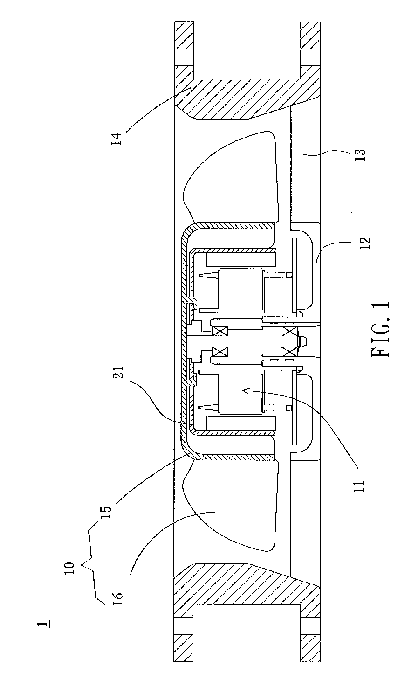
[0024]FIG. 1 is a cross-sectional view of a fan according to an embodiment of the present invention. Referring to FIG. 1, the fan 1 includes at least an impeller 10, a motor 11, base 12, several ribs 13, and frame 14. The motor 11 is disposed within the frame 14 and is disposed on the base 12 for driving the impeller 10 to rotate. The ribs are disposed between and connect the base 12 and the frame 14. The impeller 10 includes a hub 15 and a plurality of blades 16 disposed around the hub 15.

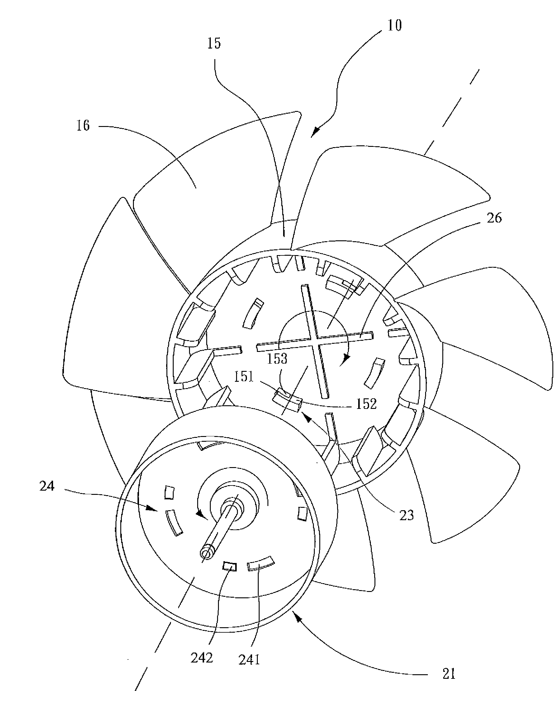
[0025]Referring both to FIG. 1 and FIG. 2, FIG. 2 is a three-dimensional view showing the impeller and the rotor housing of the fan in FIG. 1. The motor 11 has a rotor housing 21, which is coupled with the hub 15. The rotor housing 21 has a cylindrical shape, but not limited thereto, for example, an...


PUM


Abstract

A fan includes an impeller, a motor, a plurality of first engaging members and a plurality of second engaging members. The impeller includes a hub and a plurality of blades disposed around the hub. The motor includes a rotor housing coupled with the hub, and the motor is for driving the impeller to rotate. The first engaging members are disposed on an inner side of the top surface of the hub, and the second engaging members are disposed on the top surface of the housing. When the impeller and the rotor housing are assembled, the second engaging members are disposed corresponding to the first engaging members, so that parts of the first engaging members are engaged into and assembled with the second engaging members.

Description

CROSS REFERENCE TO RELATED APPLICATIONS[0001]This Non-provisional application claims priority under 35 U.S.C. §119(a) on Patent Application No(s). 096107618, filed in Taiwan, Republic of China on Mar. 6, 2007, the entire contents of which are hereby incorporated by reference.BACKGROUND OF THE INVENTION[0002]1. Field of Invention[0003]The present invention relates to a fan and, in particular to a fan that does not involve the thermal welding process and has good thermal dissipating effects.[0004]2. Related Art[0005]Fans are often used to dissipate heat produced by an electronic system or device. The fan includes a motor to drive the impeller to rotate. Therefore, the combining strength and means between the motor and the impeller directly affect the reliability of the fan.[0006]Conventionally, when the motor and the impeller are assembled together, the impeller uses several protrusions disposed on the inner surface of the hub passing through the corresponding holes formed on the roto...

Claims


Application Information

Patent Timeline
Patent Type & Authority Applications(United States)
IPC IPC(8): F04D29/58F04D29/60
CPCF04D29/329F04D29/263
Inventor CHEN, YI-LINHUNG, YA-HUIHSIEH, MING-KAILIN, LI-CHEN
Owner DELTA ELECTRONICS INC
Learn More