
Aerial detection of threatening military devices

a military device and aerial detection technology, applied in the field of electronic detection of improvised explosive devices and underground threats, can solve the problems of difficult countermeasures, secondary field detection in the presence of much larger primary field components,

Inactive Publication Date: 2008-09-11
STOLAR
View PDF36 Cites 27 Cited by
  • Summary
  • Abstract
  • Description
  • Claims
  • Application Information

AI Technical Summary

Benefits of technology

[0017]An advantage of the present invention is that a system is provide warnings of military threats ahead.
[0018]A further advantage of the present invention is a system is provided for detecting underground installations.
[0019]A still further advantage of the present invention is that a method is provided for sweeping a large area for suspicious wiring and buried installations.

Problems solved by technology

A significant instrument design issue is the detection of the secondary fields in the presence of the much larger primary field components.
This has proved to be difficult to counter.

Method used


Image

  • Aerial detection of threatening military devices
  • Aerial detection of threatening military devices
  • Aerial detection of threatening military devices

Examples


Embodiment Construction

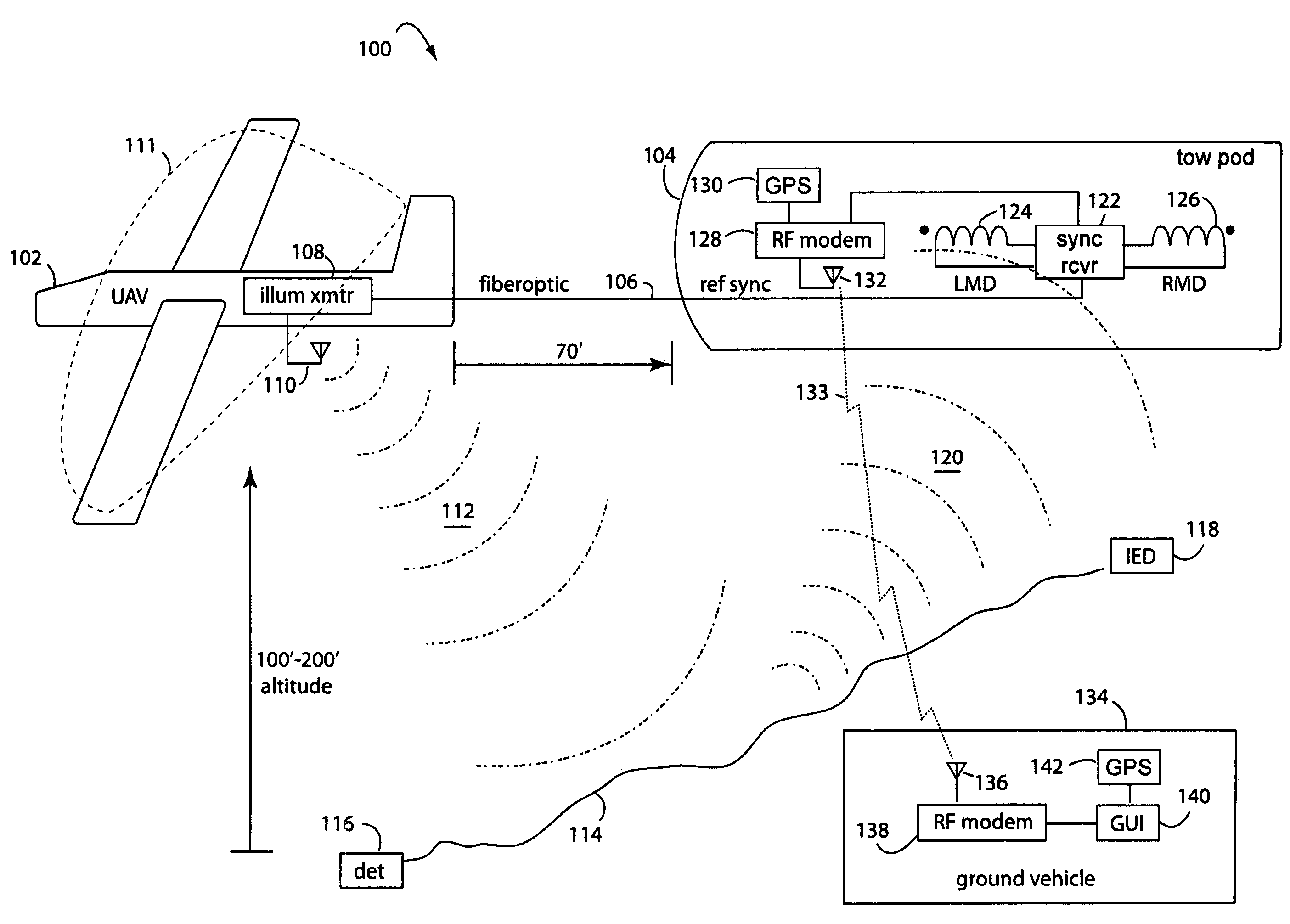
[0027]A gradiometer antenna array may comprise two ferrite-core magnetic dipole antennas (LMD and RMD) electrically coupled and 180-degrees out of phase. This is called the differential mode of operation. For maximum primary wave cancellation, the antennas are coaxial, antenna rod axes along same axis, and oriented on a base line perpendicular to an intended target's trend. The magnetic dipole antennas may also be connected in the summation mode of operation. In this case, the instrument would not operate as a gradiometer, but as a single magnetic dipole. LMD and RMD antennas may be configured as vertical or horizontal magnetic dipoles. During field tests, a horizontal magnetic dipole configuration was used. The instrumentation used a central electronics enclosure and telescoping antenna assembly enclosed in fiberglass. The antenna assembly tubing had a center section with the synchronization and calibration antenna (SMD). Measured data was transmitted to a remote lap-top computer v...


PUM


Abstract

An aerial electronic system for detection of surface and underground threats comprises an electromagnetic (EM) gradiometer flown aloft over the possible ground and underground threats to a convoy. The EM gradiometer is disposed in a Styrofoam torpedo shaped pod that is towed in flight behind an airplane. An illumination transmitter and loop antenna mounted to the airplane radiate a primary EM wave that travels down to the ground surface and penetrates beneath. Frequencies of 80 KHz to 1 MHz are selected according to whether the targets are laying on the surface or deeply buried. Detonation wire pairs, buried cables and pipes, and other conductors will re-radiate a secondary wave that can be sensed by the EM gradiometer. A reference sample of the transmitter signal is carried down a fiberoptic from the airplane to the towed pod. This signal is used in the synchronous detection to measure the secondary EM wave phase.

Description

[0001]This Application is a Continuation-In-Part of U.S. patent application 11 / 405,602, filed Apr. 17, 2006, titled AERIAL DETECTION OF ROADSIDE IMPROVISED EXPLOSIVE DEVICE, docket MLF 654-21, and incorporated by reference in whole. This Application also claims priority from U.S. Provisional Patent Application 60 / 671,946, filed Apr. 18, 2005, and U.S. Provisional Patent Application 60 / 853,538, filed Oct. 23, 2006, titled LOOK-AHEAD RADAR AND HORIZON SENSING FOR COAL CUTTING DRUMS AND HORIZONTAL DIRECTIONAL DRILLS, docket MLF 654-24, and both are incorporated by reference herein.BACKGROUND OF THE INVENTION[0002]1. Field of the Invention[0003]The present invention relates to electronic detection of improvised explosive devices and underground threats, and more particularly to the use of airborne electromagnetic gradiometers that use synchronous detection to image detonation cables and underground facility wiring and piping.[0004]2. Description of Related Art[0005]Primary electromagnet...

Claims


Application Information

Patent Timeline
IPC IPC(8): G01V3/16
CPCG01V3/17
Inventor STOLARCZYK, LARRY G.BAUSOV, IGORMAIN, RICHARD B.
Owner STOLAR
Learn More