Hydraulic Transaxle

a transaxle and center-pivoting technology, applied in fluid gearings, transportation and packaging, gearing, etc., can solve the problems of increased height of the entire vehicle traveling system including the transaxle, disadvantageous assembly and compactness, and operator discomfort, and achieve sufficient ground clearance and small vertical length

Inactive Publication Date: 2008-09-11
KANZAKI KOKYUKOKI MFG
View PDF44 Cites 0 Cited by
  • Summary
  • Abstract
  • Description
  • Claims
  • Application Information

AI Technical Summary

Benefits of technology

[0014]A main object of the present invention is to provide a compact center-pivoted transaxle mounted onto a vehicle frame so as to be turnable around an axis oriented in a fore-and-aft direction of a vehicle, wherein the transaxle, including a pair of hydraulic motors for driving respective left and right wheels, has a small vertical length while ensuring a sufficient ground clearance therebelow.

Problems solved by technology

However, the height of the left and right hydraulic motors projecting upward from the axle casing directly causes increase of the height of an entire vehicle traveling system including the transaxle.
Furthermore, the hydraulic motors, disposed out of the axle casing and oriented perpendicular to the axle casing, are disadvantageous in assembly and compactness.
However, in this art, the front wheels are not accelerated before a manipulation degree of a steering manipulator reaches the predetermined value.
Namely, the reaction of front-wheel acceleration does not cover the entire manipulation range of the steering manipulator, whereby an operator may feel discomfort.
Furthermore, the front-wheel transaxle including the friction clutch complicates a vehicle configuration and increases a vehicle weight.
Further, the vehicle is disadvantageous to have a mid-mount mower below a middle portion thereof because the drive shaft narrows a space for attachment and maintenance of the mower.
Another disadvantage of the drive shaft is to prevent lowering a footplate of the vehicle.
Further, the transmission system interposed between the drive shaft and the front wheels includes a mechanical differential unit requiring a large space in the axle casing, thereby, reducing a ground clearance.

Method used


Image

  • Hydraulic Transaxle
  • Hydraulic Transaxle
  • Hydraulic Transaxle

Examples


embodiment 1

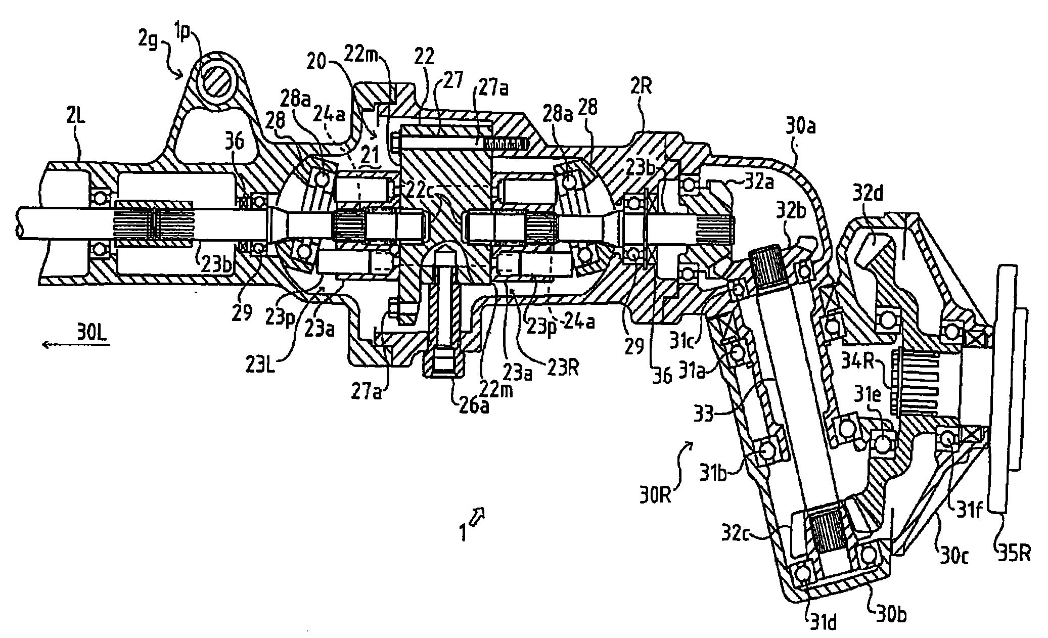
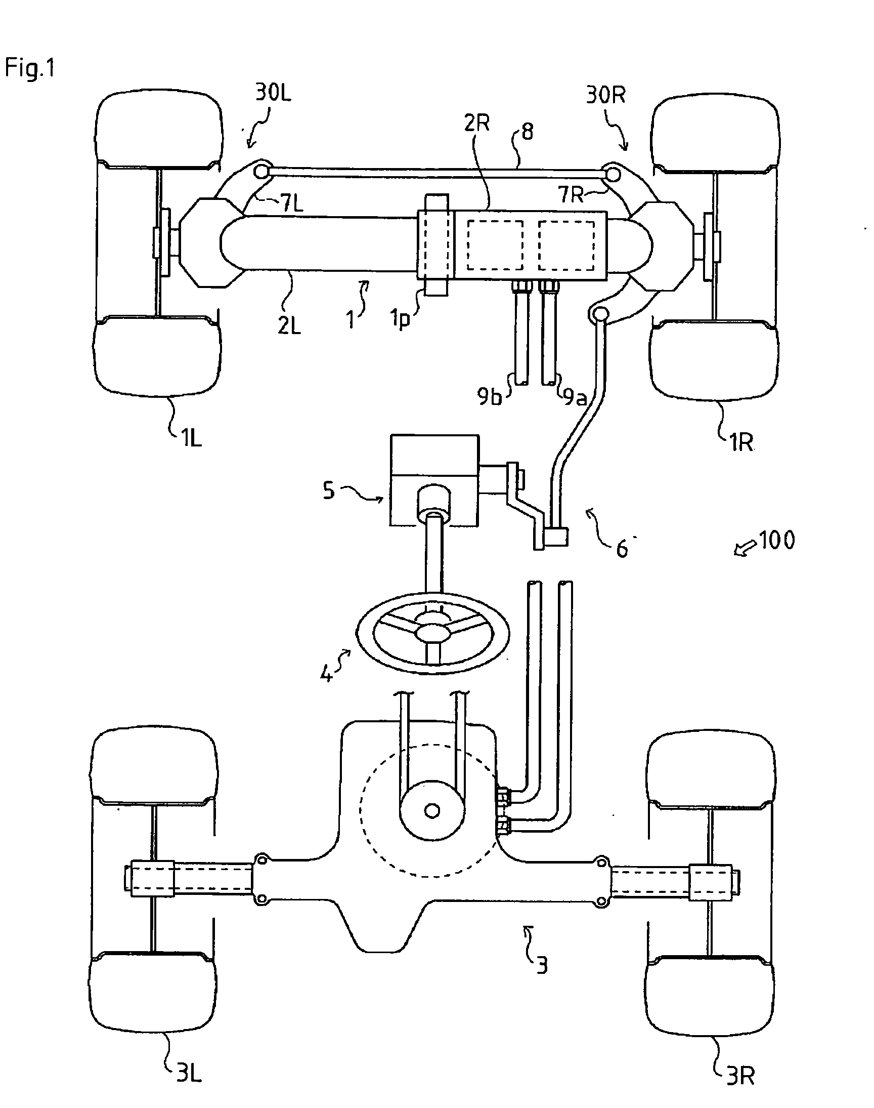
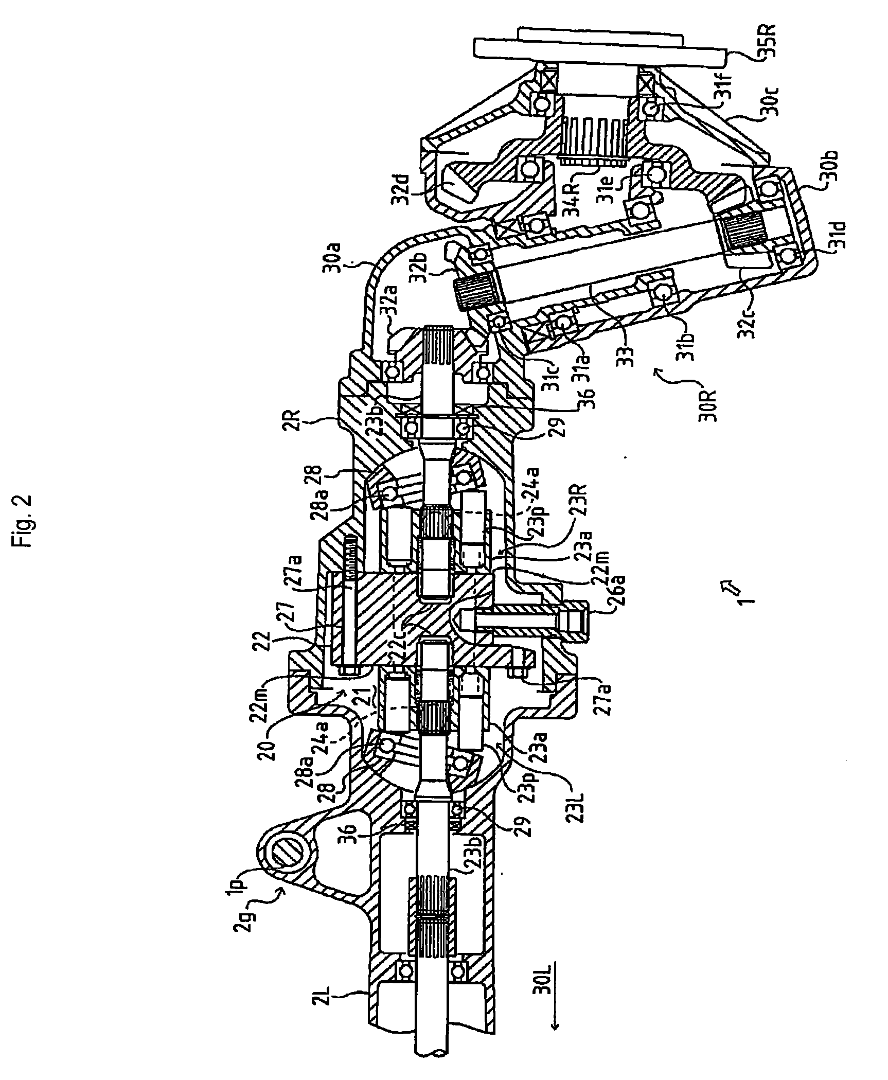
[0132]First, a description will be given of transaxle 1 according to Embodiment 1.

[0133]As shown in FIG. 2, transaxle 1 consists of a hydraulic drive unit 20 and a pair of left and right wheel support units 30L and 30R drivingly and steerably supporting respective left and right front wheels 1L and 1R. Hydraulic drive unit 20 is comprised of a left axle casing 2L, a right axle casing 2R, a housing 21, a center section 22, a pair of left and right variable displacement hydraulic motors 23L and 23R, and a linkage system 24. Left axle casing 2L serves as a first axle casing part which is provided with a suspended portion 2g suspended by a center pin 1p fixed at the laterally substantially middle portion of the vehicle frame. Right axle casing 2R serves as a second axle casing part whose left end surface is joined to a flange portion formed on the right end surface of left axle casing 2L. Housing 21 is formed at a joint portion between left and right axle casings 2L and 2R. Center secti...

embodiment 2

[0165]Description will now be given of transaxle 1 according to Embodiment 2.

[0166]FIG. 6 shows a hydraulic circuit diagram of the traveling drive system of the vehicle according to Embodiment 2.

[0167]In this configuration, the pair of hydraulic motors 23L and 23R in hydraulic drive unit 20 are of the variable displacement type, having movable swash plates 28 and 28. The flow rate of hydraulic oil supplied to center section 22 for driving the hydraulic motors is controlled by volumetric flow control means (including flow dividing valves 42 and 42).

[0168]As shown in FIG. 6, flow dividing valves 42 and 42 are interpositioned at middle portions of respective hydraulic hoses 9a and 9b between rear transaxle 3 and control valve 45, so as to bypass a part of flow of hydraulic oil, supplied toward front transaxle 1 from hydraulic pump 40P, via respective relief circuits 42a and 42a. Also, returning oil passages 42b and 42b are provided to release pressure between control valve 45 and respe...

embodiment 3

[0172]Description will be given of transaxle 1 according to Embodiment 3.

[0173]In a configuration shown in FIG. 7, a center section 122 is inserted between joint surfaces of left and right axle casings 2L and 2R.

[0174]As shown in FIGS. 7 and 8, center section 122 is formed with left and right annular stepped portions 122a ad 122a having respective distally projecting vertical motor attachment surfaces 122m and 122m. Axle casings 2L and 2R are formed with flanges 2J and 2J expanded from the joint surfaces thereof. Flanges 2J and 2J are fitted onto respective annular stepped portions 122a and 122a so as to fix motor attachment surfaces 122m and 122m in position.

[0175]Furthermore, in a sectional side view, bolt holes 87, 87 and 87 are bored laterally through center section 122 at plural positions. Bolts 87a, 87a and 87a are inserted into the respective bolt holes 87, 87 and 87 from the right axle casing 2R side, and are screwed into tapped holes in left axle casing 2L. In this way, lef...


PUM


Abstract

A transaxle (1), having a hydraulic drive unit (20) and a pair of left and right wheel support units (2L and 2R), is suspended from a vehicle frame so as to be turnable around a turning-center axis oriented in a fore-and-aft direction of a vehicle. The hydraulic drive unit (20) comprises: a pair of left and right hydraulic motors (23L and 23R) having respective left and right horizontal motor shafts (23b); a center section (22) formed therein with an oil passage for hydraulically connecting at least one of the hydraulic motors to a hydraulic pump, the center section having motor attachment surfaces onto which the hydraulic motors are attached; and a pair of left and right axle casings (2L and 2R) containing the respective hydraulic motors and supporting the respective motor shafts. The pair of wheel support units (30L and 30R), supporting respective left and right travel wheels (1L and 1R), are joined to respective outer ends of the left and right axle casings, and drivingly connected to the respective motor shafts (23b).

Description

CROSS-REFERENCE TO RELATED APPLICATION[0001]This application is a divisional of U.S. application Ser. No. 10 / 917,557, filed Aug. 13, 2004, the entire disclosure of which is hereby incorporated herein by reference thereto.BACKGROUND OF THE INVENTION[0002]1. Field of the Invention[0003]The present invention relates to a center-pivoted transaxle, which is mounted onto a vehicle frame so as to be turnable around an axis oriented in a fore-and-aft direction of a vehicle, being applicable for various four-wheel-drive / two-wheel-steering (4WD / 2WS) industrial vehicles and four-wheel-drive / four-wheel-steering (4WD / 4WS) industrial vehicles, such as agricultural tractors, riding lawn mowers and construction vehicles. The transaxle can be provided for driving front wheels of a tractor, for example.[0004]2. Background Art[0005]Conventionally, there are many disclosed characteristic arts concerning various industrial vehicles equipped with a hydraulic transaxle, e.g., agricultural tractors, riding...

Claims


Application Information

Patent Timeline
Patent Type & Authority Applications(United States)
IPC IPC(8): B60B35/16B60K17/04B60K17/10B60K17/356B62D7/18B62D9/00B62D11/00F16H39/14
CPCB60K17/043B60K17/105B60K17/356B60Y2200/221F16H39/14B62D7/18B62D9/002B62D11/001B60Y2200/223
Inventor IWAKI, KOJIISHII, NORIHIROSAKIKAWA, SHIGENORIMIZUKAWA, KATSUMOTOKAWAKAMI, MANABUNAGATA, KENTARO
Owner KANZAKI KOKYUKOKI MFG
Why Eureka
Try Eureka