
Manually Operated Venetian Blind and Method of Darkening a Room

a venetian blind and manual operation technology, applied in the field of venetian blinds, can solve the problems of affecting the appearance of the room, the cords supporting the blinds are entangled, and the mechanism is complex and requires maintenance or replacement, so as to achieve the effect of increasing the inclination of the room, increasing the surface area, and increasing the reliability

Inactive Publication Date: 2008-09-11
BEN DAVID AVIGDOR
View PDF49 Cites 22 Cited by
  • Summary
  • Abstract
  • Description
  • Claims
  • Application Information

AI Technical Summary

Benefits of technology

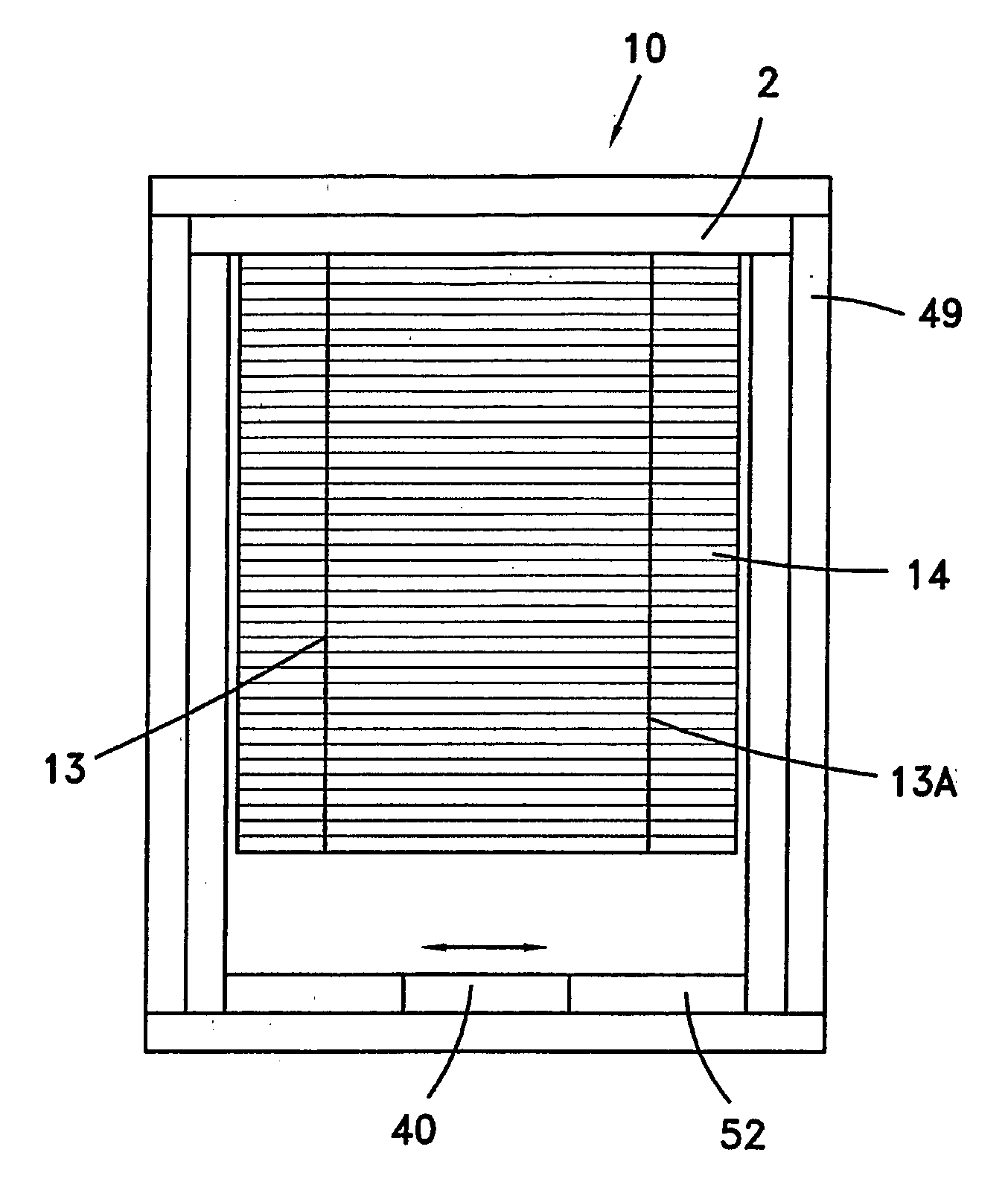
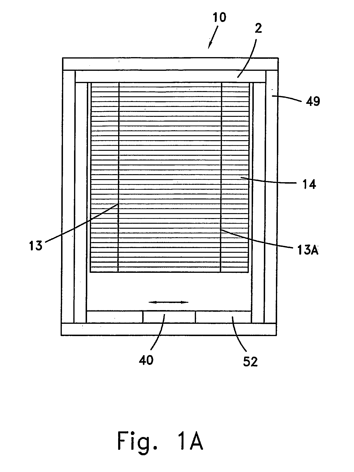
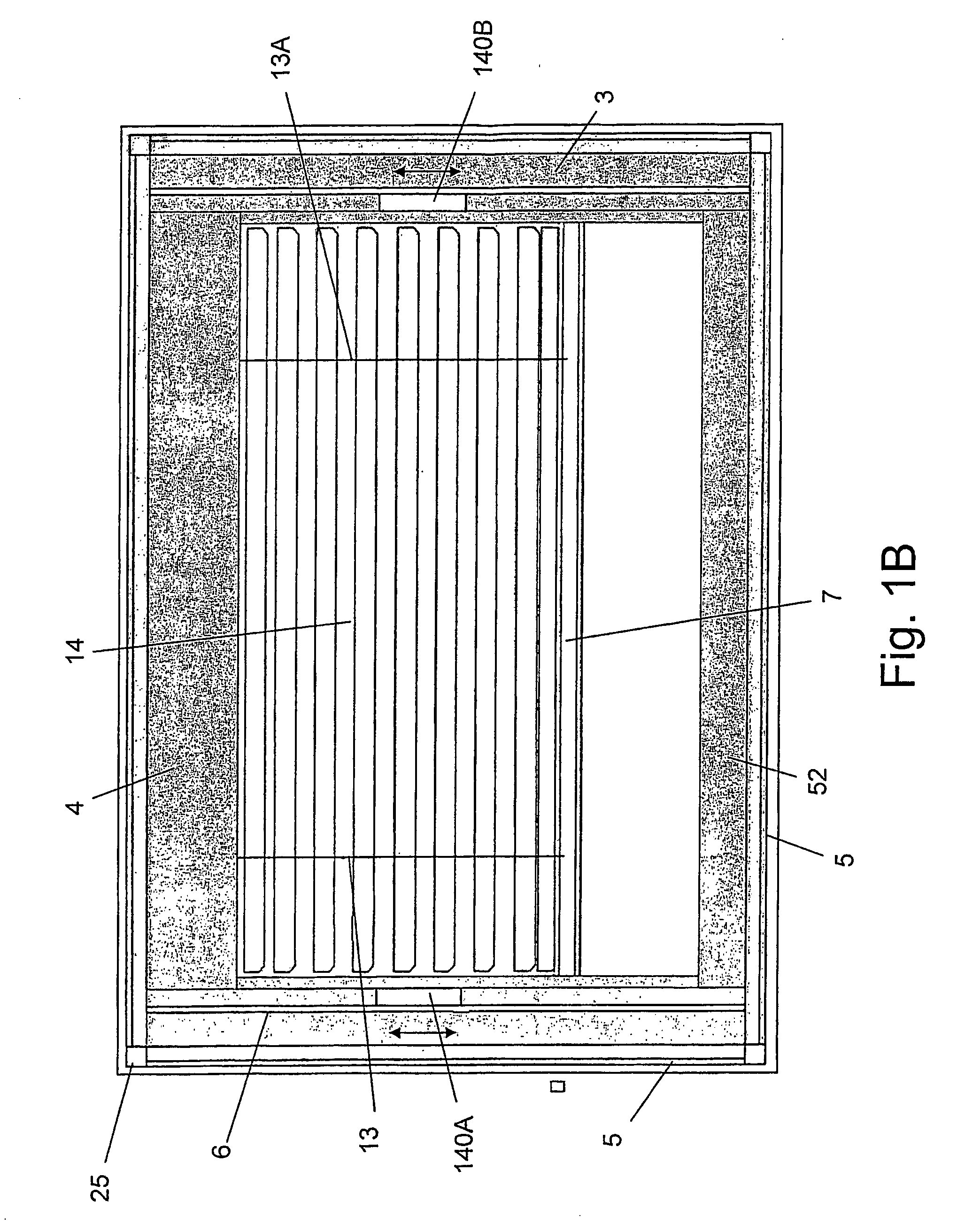
[0029]By winding the central cords about the ball bearings housed in the bearing housing and bearing block, respectively, and then affixing the ends of each central cord to the stabilizer, the central cords are subjected to a frictional force significantly less than that of the prior art. While prior art blinds require a full 100% stroke length to achieve a complete raising / lowering of the slats, the displacement of the actuator of the present invention is advantageously only 40% of the distance to which the longitudinally lowest slat is raised or lowered. Consequently, the slats of a blind having a surface area of up to 5 square meters can be lowered or raised effortlessly and speedily.
[0033]In contrast, the tilting device of the present invention is configured such that two outer cords are affixed to a corresponding tilting device by two affixation means, respectively, that retain the cords in an essentially vertical disposition from the headrail to the lower support member. The weight of the slats is therefore more evenly distributed than in the prior art, allowing the slats of a blind having a higher surface area than has been known heretofore to be tilted with greater reliability and without use of a gear train.
[0036]In one embodiment, the two outer cords are affixed to a corresponding tilting device by two affixation means, respectively, positioned along the transversal centerline of the rectangular face thereof in such a way that an outer cord contacts one of said two opposed faces when said rectangular face is parallel to said at least one support surface. Each affixation means comprises an aperture bored through the rectangular face and a corresponding nail having radial protrusions, said nail being received in said aperture. The radial protrusions are adapted to press an outer cord onto the wall of the aperture and to thereby retain the pressed portions of the outer cord in a fixed position relative to the rectangular face of the tilting device.
[0047]The first outer cord presses the plurality of slats and thereby assists in further increasing the inclination of the slats. Due to the increased inclination of the slats, the spacing between the first and second outer cords changes from 17 mm when the slats are in a completely open position to 3 mm when the slats are in a completely closed position.
[0050]In one aspect, the step of securing a cord guide assembly to a frame component comprises the steps of:a) providing a substantially rectilinear cord guide assembly having a transversally oriented and inwardly positioned face from which the cord guide longitudinally protrudes, two longitudinally oriented sides, two laterally oriented sides, and four legs, each of said legs abutting a corresponding corner of said cord guide assembly and the longitudinally outward end of each of said legs terminating with a wedge-shaped portion, wherein each of said laterally oriented sides is formed with an arcuate opening on which an annular protrusion of a tilting device is to be mounted and with a substantially rectangular opening which is formed laterally outwardly from the corresponding arcuate opening, thereby affording the corresponding laterally oriented side with increased flexibility;

Problems solved by technology

They may have a complex mechanism which requires maintenance or replacement, or may have an expensive automatic control system.
If the longitudinal axis of the blind arrangement were not in an essentially vertical disposition, some of the blinds would touch the glazing, causing the cords which support the blinds to become entangled.
As a result, the weight of the slats is concentrated disproportionally more on the spacer and the uppermost slat than on the other slats, causing the slats to change their relative position, or even to fail, over the course of time.
The tilting mechanism is usually a gear train that adds to the cost of the blind unit.
Also, due to the angle of the cords the blinds cannot completely close and invariably only 75% of the incoming light is blocked.
The gear train is adapted to tilt the slats, but the Venetian blind structure is not provided with a means to raise or to lower the slats.
Also the addition of the gear train adds to the cost of producing and assembling the blind structure.
The complexity and cost of the apparatus is increased, due to the transmission system, as well as the actuator that is external to the double glazing unit.
The apparatus of the actuation unit adds to the cost of the Venetian blind.

Method used


Image

  • Manually Operated Venetian Blind and Method of Darkening a Room
  • Manually Operated Venetian Blind and Method of Darkening a Room
  • Manually Operated Venetian Blind and Method of Darkening a Room

Examples


Embodiment Construction

[0093]The present invention is a novel manually operated internal Venetian blind with a surface area of up to 5 square meters that can be lowered / raised and tilted effortlessly and speedily, whose operating mechanism can be adjusted to the dimensions of the blind, and which can be inverted without disarray of the slats and of the cords.

[0094]The first embodiment of the present invention relates to an internal Venetian blind for tilting a plurality of slats. Several prior art internal Venetian blinds comprise a tilting mechanism in the headrail in which outer cords of a ladder braid are wound around a cylindrical element, which is generally driven by gears, or any other type of transmission in communication with an actuator external to the Venetian blind. Since this cylindrical element is housed within the headrail, the circumference of the cylindrical element is laterally spaced from the lateral periphery of the slats across which the outer cords extend. Spacers placed on the transv...


PUM


Abstract

In one embodiment, a manually operated internal Venetian blind for raising / lowering a plurality of slats is disclosed, and comprises a stationary bearing housing, a longitudinally displaceable bifurcated bearing block, a counterweight interconnected to the bearing block and housing at least one internal magnet, and a first linearly displaceable actuator disposed outwardly to one of two glass sheets and provided with at least one external magnet at a fixed distance from the internal magnet. The displacement of the first actuator is significantly less than the displacement of the longitudinally lowest slat due to the winding of central cords around a ball bearing housed within the bearing block. In another embodiment, a device for tilting the slats to which two outer cords are affixed is provided with two laterally oriented sides and an annular protrusion rotatably supported by a suitable assembly secured to a support surface and transversally extending outwardly from each laterally oriented side, such that the tilting device is rotatable about a transversal axis coincident with the axis of the annular protrusions. An external blind is also disclosed.

Description

FIELD OF THE INVENTION[0001]The present invention relates to the field of Venetian blinds. More particularly, the invention relates to a manually operated Venetian blind that can be lowered / raised and tilted effortlessly and speedily by means of a novel, reliable, and cost-effective operating mechanism.BACKGROUND OF THE INVENTION[0002]Shading devices have been traditionally used to reduce the area of glazing which is exposed to an influx of solar radiation.[0003]Operable shading devices mounted exterior to windows are designed to control the incoming solar radiation. They may have a complex mechanism which requires maintenance or replacement, or may have an expensive automatic control system.[0004]Other types of shading devices, such as roller shades, curtains or Venetian blinds, are installed within the interior of a building and are adapted to reflect incoming solar radiation back through the window before it can be absorbed and converted to heat. Recently, internal blinds, i.e. V...

Claims


Application Information

Patent Timeline
Patent Type & Authority Applications(United States)
IPC IPC(8): E06B9/264
CPCE06B2009/2646E06B9/264
Inventor BEN-DAVID, AVIGDOR
Owner BEN DAVID AVIGDOR
Learn More