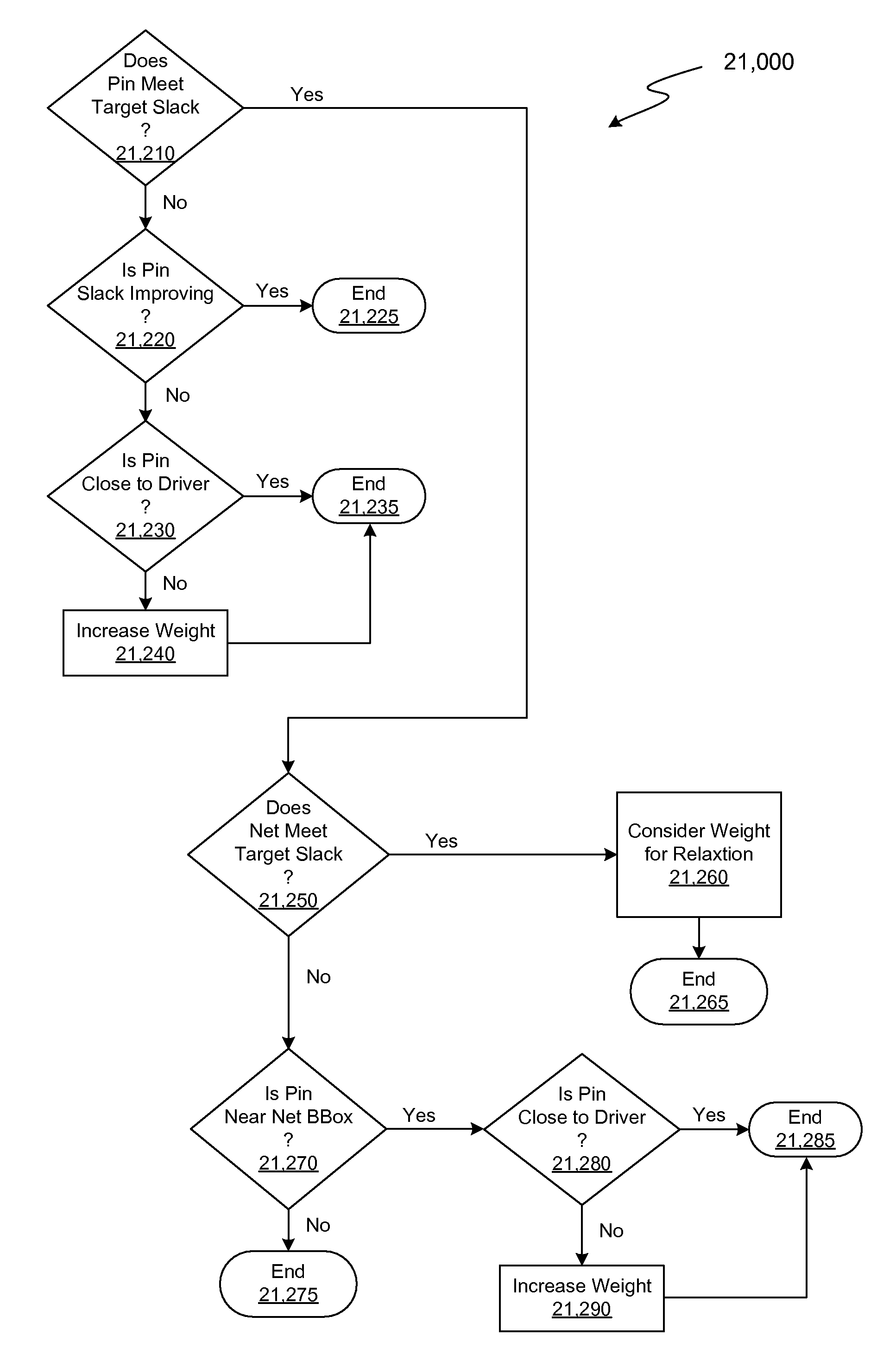
Incremental Relative Slack Timing Force Model
a technology of relative slack and force model, applied in the field of integrated circuit design, can solve the problems of time-varying complexity in the behavior (character of motion) of the moveable nodes in the netlist, and the limitation of the departure of the morphable device to its implementation,
- Summary
- Abstract
- Description
- Claims
- Application Information
AI Technical Summary
Benefits of technology
Problems solved by technology
Method used
Image

Examples
first embodiment
[0026]FIG. 5A is a flow diagram illustrating selected details of resource reconciliation, as a first example of legalization.
second embodiment
[0027]FIG. 5B is a flow diagram illustrating selected details of resource reconciliation, as a second example of legalization.
[0028]FIG. 5C is a flow diagram illustrating selected details of an embodiment of partitioning.
[0029]FIG. 6 is a flow diagram illustrating selected details of an embodiment of detailed placement (also referred to as detail placement elsewhere herein).
[0030]FIG. 7A is a flow diagram illustrating selected aspects of an embodiment of delay path reduction and minimization, as an example of timing closure.
[0031]FIG. 7B illustrates a conceptual view of selected elements of an embodiment of timing-driven forces.
[0032]FIG. 7C illustrates a spatial organization of the driver and the coupled loads of FIG. 7B.
[0033]FIG. 7D illustrates an embodiment of Net Boundary Box (NBB) estimation of routing to cover the driver and the loads of FIG. 7C.
[0034]FIG. 7E illustrates an embodiment of a rectilinear Steiner Route Tree (SRT) estimation to cover the driver and loads of FIG. 7...
PUM
 Abstract
Description
Claims
Application Information
 - R&D
- Intellectual Property
- Life Sciences
- Materials
- Tech Scout
- Unparalleled Data Quality
- Higher Quality Content
- 60% Fewer Hallucinations
Browse by: Latest US Patents, China's latest patents, Technical Efficacy Thesaurus, Application Domain, Technology Topic, Popular Technical Reports.
© 2025 PatSnap. All rights reserved.Legal|Privacy policy|Modern Slavery Act Transparency Statement|Sitemap|About US| Contact US: help@patsnap.com