
Computer-readable medium storing display control program and mobile terminal

a computer-readable medium and control program technology, applied in computing, instruments, substation equipment, etc., can solve the problems of inability to display on the built-in display the produced screen data, the inability to operate with the naked eye, and the inconvenient operation of the display screen

Inactive Publication Date: 2008-09-04
FUJITSU LTD
View PDF10 Cites 76 Cited by
  • Summary
  • Abstract
  • Description
  • Claims
  • Application Information

AI Technical Summary

Benefits of technology

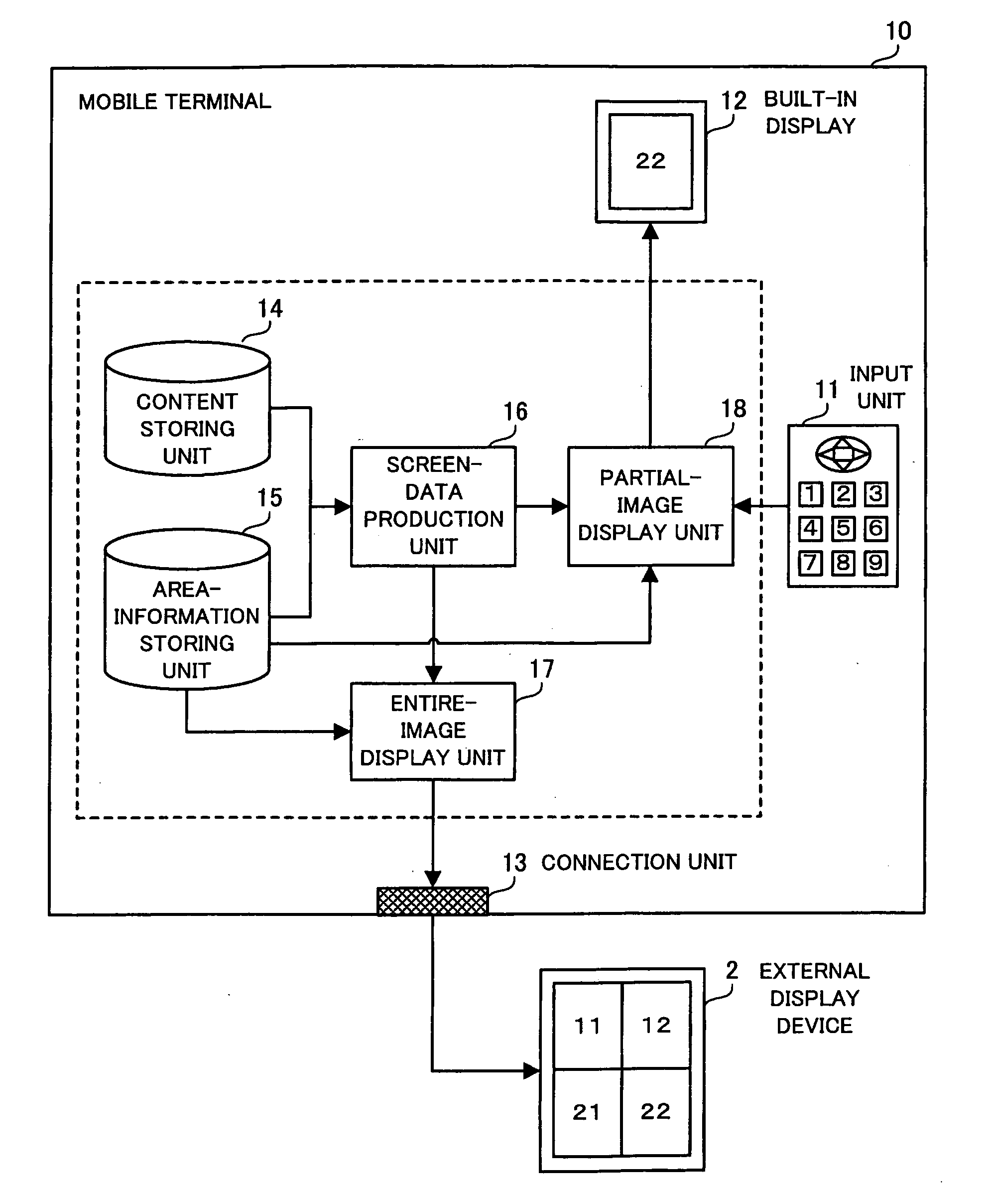
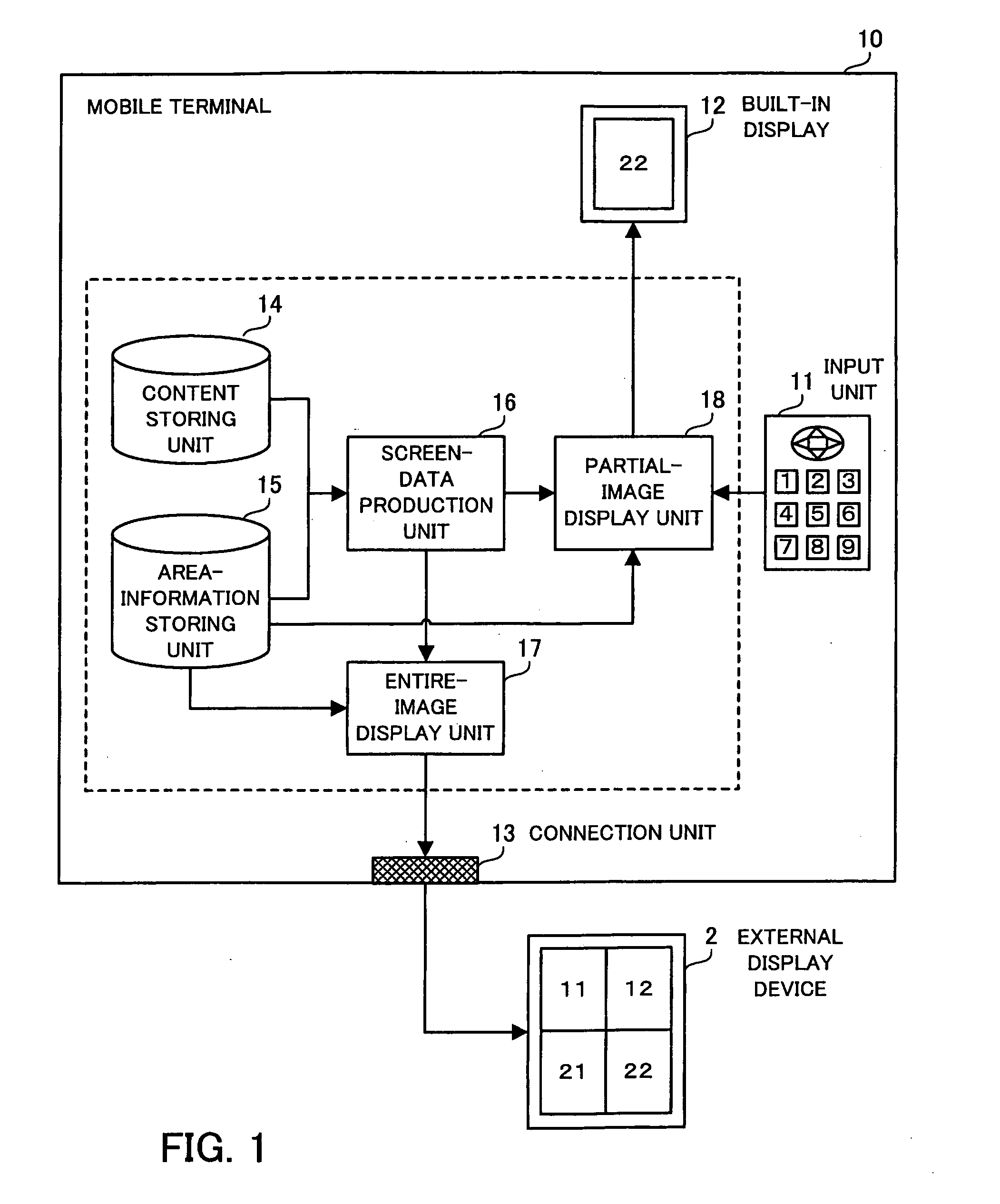
[0010]The present invention is made in view of the above problems, and the first object of the present invention is to provide a computer-readable medium storing a display control program for a mobile terminal, where the display control program assists a user of the mobile terminal so that the user can precisely and easily perform a screen operation of the mobile terminal even when the display area of a built-in display of the mobile terminal is smaller than the display area of an external display device.
[0011]In addition, the second object of the present invention is to provide a mobile terminal controlled by a display control program which assists a user of the mobile terminal so that the user can precisely and easily perform a screen operation of the mobile terminal even when the display area of a built-in display of the mobile terminal is smaller than the display area of an external display device.

Problems solved by technology

However, in the case where the display area of the built-in display is smaller than the display area of the external display device, the convenience of operation of the display screen deteriorates.
That is, when screen data is produced so as to fit the display area of the external display device, it is impossible to display on the built-in display the produced screen data as they are.
In the case where the built-in display displays the reduced image of the produced screen data, the size of displayed characters is reduced, so that it is difficult to identify with the naked eye an item to be operated.
However, the above technique disclosed in Japanese Unexamined Patent Publication No. 10-039981 has a drawback that operation errors by the user are likely to occur.

Method used


Image

  • Computer-readable medium storing display control program and mobile terminal
  • Computer-readable medium storing display control program and mobile terminal
  • Computer-readable medium storing display control program and mobile terminal

Examples


first embodiment

2. First Embodiment

[0050]Hereinbelow, details of the preferred embodiments are explained with reference to FIGS. 2 to 21. First, the first embodiment is explained with reference to FIGS. 2 to 14.

2.1 System Configuration

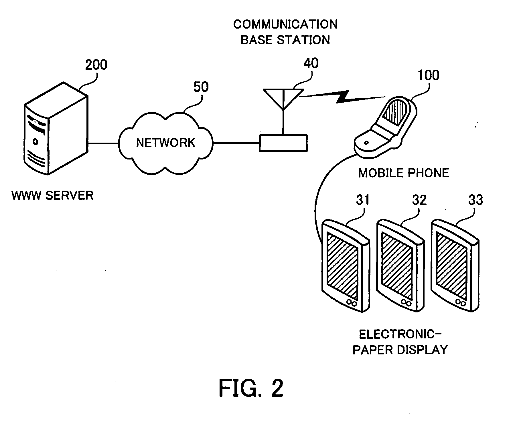
[0051]FIG. 2 is a diagram illustrating an example of a configuration of a content delivery system according to a first embodiment of the present invention. The content delivery system according to the first embodiment enables each mobile phone to acquire a content item from a WWW server through a network and display the content item on an electronic-paper display connected to the mobile phone. The content delivery system of FIG. 2 is constituted by a mobile phone 100, a WWW server 200, electronic-paper displays 31, 32, and 33, a communication base station 40, and a network 50. The WWW server 200 and the communication base station 40 are connected to the network 50, and can communicate with each other. In addition, the communication base station 40 and the mobile phone...

second embodiment

3. Second Embodiment

[0113]Next, the second embodiment is explained with reference to FIGS. 15 to 18. The mobile phone according to the second embodiment is configured so that the user can recognize the range of the area currently displayed on the built-in display of the mobile phone at the sight of the electronic-paper display. The following explanations are focused on the differences from the first embodiment, and similar features to the first embodiment are not explained.

[0114]In the following explanations, a content delivery system according to the second embodiment is assumed to have a system configuration similar to the configuration of the content delivery system according to the first embodiment (as illustrated in FIG. 2), although a mobile phone 100a, instead of the mobile phone 100 according to the first embodiment, is used in the content delivery system according to the second embodiment. Part of the processing functions of the mobile phone 100a according to the second emb...

third embodiment

4. Third Embodiment

[0143]Next, the third embodiment is explained with reference to FIGS. 19 to 21. The mobile phone according to the third embodiment is configured to enable an electronic-paper display to display a magnified image of the area displayed on the built-in display. The following explanations are focused on the differences from the first embodiment, and similar features to the first embodiment are not explained.

[0144]In the following explanations, a content delivery system according to the third embodiment is assumed to have a system configuration similar to the configuration of the content delivery system according to the first embodiment (as illustrated in FIG. 2), although a mobile phone 100b, instead of the mobile phone 100 according to the first embodiment, is used in the content delivery system according to the third embodiment. Part of the processing functions of the mobile phone 100b according to the third embodiment which are realized by execution of a program fo...


PUM


Abstract

A medium storing a program for display control. When the program is executed by a computer realized in a mobile terminal, the mobile terminal operates as follows. An area-information storing unit stores information on a first display area of an external display device and a second display area of a built-in display. A screen-data production unit acquires content to be displayed, and produces screen data corresponding to the first display area. An entire-image display unit divides the screen data into partial areas each corresponding to the second display area, adds to the entire screen data area-display data indicating the extent of each partial area and a corresponding identifier, and displays the screen data on the external display device. On receipt of an identifier, a partial-image display unit extracts a portion of the screen data for a partial area corresponding to the identifier, and displays the portion on the built-in display.

Description

CROSS-REFERENCE TO RELATED APPLICATIONS[0001]This application is based upon and claims the benefits of priority from the prior Japanese Patent Application No. 2007-044496 filed on Feb. 23, 2007, the entire contents of which are incorporated herein by reference.BACKGROUND OF THE INVENTION[0002]1. Field of the Invention[0003]The present invention relates to a computer-readable medium storing a display control program and a mobile terminal using the display control program, where the display control program controls information displayed on both of a built-in display and an external display device.[0004]2. Description of the Related Art[0005]Recently, the technology of manufacturing display devices (which display characters and images) has dramatically advanced, and various types of display devices have been developed. For example, the recently developed display devices include a type which realizes a high frame rate and is suitable for display of dynamic images, a type which has a lar...

Claims


Application Information

Patent Timeline
IPC IPC(8): H04B1/38H04M1/00
CPCG06F3/0481G06F3/0485G06F3/1454G06F2203/04803G06F2203/04806G09G5/14H04M1/72527G09G2340/0464G09G2340/10G09G2340/12G09G2340/145G09G2370/16G09G2380/14G09G2340/0407H04M1/72409
Inventor HASHIMOTO, FUMIYUKIOKADA, YOSHIYUKIKAGEYAMA, YOSHIAKITAMURA, SHINOBUMATSUDA, RUMIKOSATOSASAKI, SHIGENORI
Owner FUJITSU LTD
Learn More