
Catalyst cleaning tool

a catalyst and cleaning tool technology, applied in the direction of cleaning using liquids, machines/engines, separation processes, etc., can solve the problems of high cost, large time consumption, and clogging of scr units, and achieve the effect of maximizing the air directed into honeycomb cells

Inactive Publication Date: 2008-09-04
UNDERWOOD JAMES MARK
View PDF13 Cites 1 Cited by
  • Summary
  • Abstract
  • Description
  • Claims
  • Application Information

AI Technical Summary

Benefits of technology

The solution provides a cost-effective and efficient method for cleaning SCR units, reducing downtime and expenses by allowing on-site cleaning of honeycomb cells, improving the removal of debris compared to existing methods.

Problems solved by technology

At some point, the SCR units become clogged with sulfur oxides (SOx) and / or fly ash.
The greater the amount of sulfur in coal, the more frequently the SCR unit becomes clogged.
This removal and transportation utilizes a large amount of time and is very expensive.
Both are inefficient methods for removing SOx and fly ash.

Method used


Image

  • Catalyst cleaning tool
  • Catalyst cleaning tool
  • Catalyst cleaning tool

Examples


Embodiment Construction

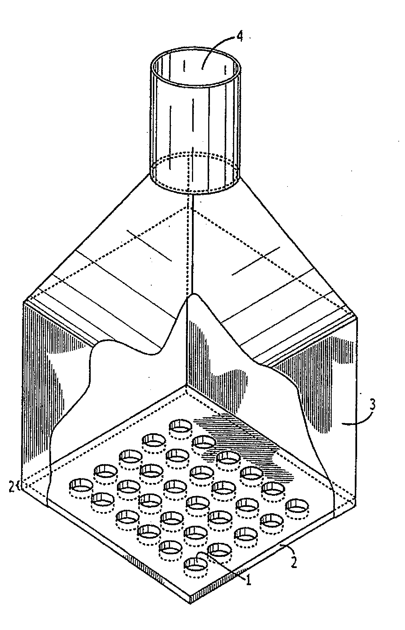
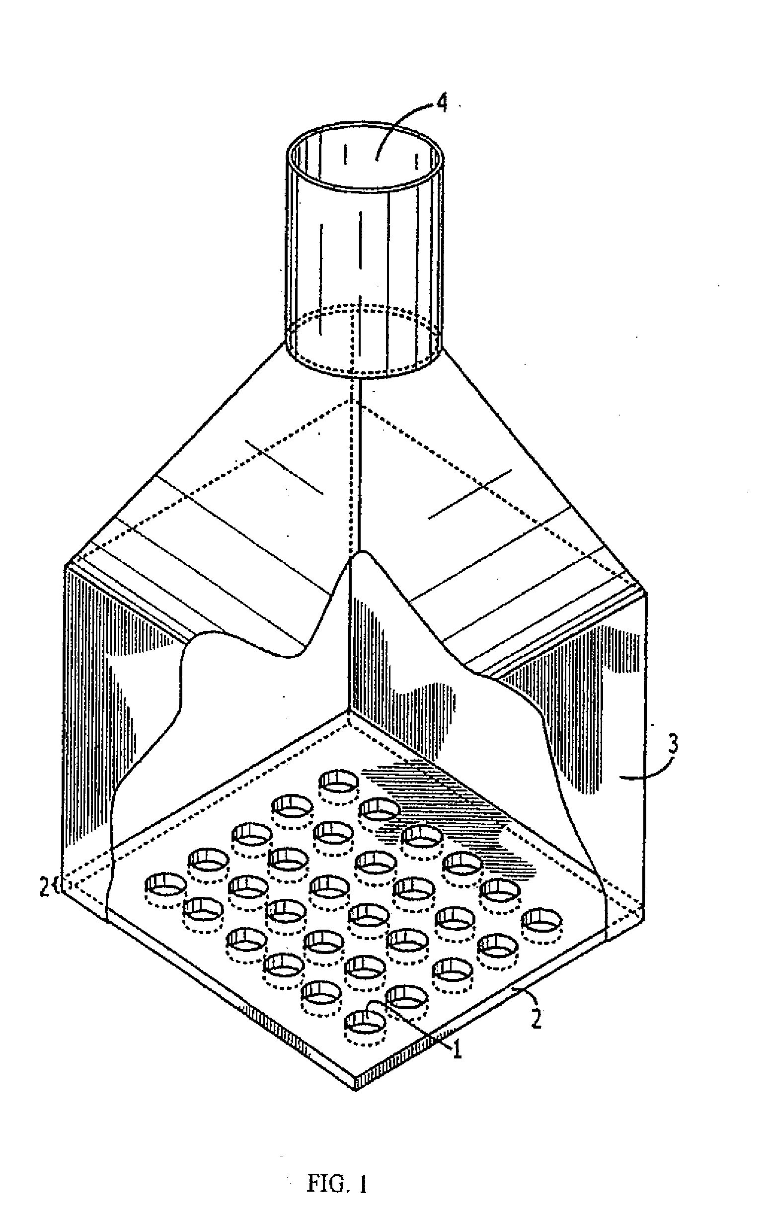
[0023]To make it possible to implement a cleaning method according to the invention, a catalyst cleaning tool as illustrated in FIG. 1 is produced which comprises an inlet 4, a housing 3, a plurality of spaced orifices 1, and a layer of polymeric material 2, the bottom of which is connected to the selective catalyst reduction unit. This layer of polymeric material 2 has a cross-sectional configuration sufficient to fit adjacent to said honeycomb cells and an outlet means comprising spaced orifices 1 for directing air through each individual honeycomb cell of the SCR. The polymeric material 2 has sufficient flexibility, resiliency, and as a result a sufficient flexural modulus to maximize the delivery of air through honeycomb cells without loss to the surroundings.

[0024]In the catalyst cleaning tool according to the invention presented in FIG. 1, the device involves a means for directing air through a plurality of spaced orifices 1 into honeycomb cells of the SCR unit. The device als...


PUM


Abstract

A device for cleaning a selective catalyst reduction unit by directing air or a cleansing solution directly into or out of honeycomb cells of the selective catalyst reduction unit. The device utilizes a plurality of orifices which are sufficient in diameter and number to cleanse honeycomb cells thereby directing air or cleansing solution into or out of each individual honeycomb cell. The device also utilizes a plurality of probes which are sufficient in number and diameter to cleanse the honeycomb cells. The invention also involves a method for cleaning the honeycomb cells and a method for producing the catalyst cleaning tool.

Description

[0001]This Continuation application claims the benefit of U.S. Utility patent application Ser. No. 11 / 010,717 filed Dec. 14, 2004, the complete disclosure of which is hereby expressly incorporated by reference.BACKGROUND OF THE INVENTION[0002]1. Field of the Invention[0003]The present invention relates generally to particulate removal from selective catalyst reduction units and more particularly to cleaning fossil fuel combustion byproducts SOx and fly ash from the honeycomb cells of the selective catalyst reduction unit.[0004]2. Description of Related Art[0005]The EPA has recently promulgated a major reduction in nitrogen oxides (NOx) emissions. Predominantly coal-fired utility companies are affected by this regulation. The major method of compliance for the utilities has been use selective catalytic reduction (SCR) to reduce NOx emissions.[0006]The SCR units are designed of adsorbent material in order to catch the NOx substances prior to entrance into the atmosphere. One type of S...

Claims


Application Information

Patent Timeline
Patent Type & Authority Applications(United States)
IPC IPC(8): B08B9/027B08B3/04B08B5/02B08B9/04
CPCB01D53/8631B01D53/96F01N2260/06F01N3/05F01N3/206F01N3/04
Inventor UNDERWOOD, JAMES MARK
Owner UNDERWOOD JAMES MARK
Learn More