Deaerator and Deaerating Method

a degasification and vacuum vessel technology, applied in liquid degasification, separation of dispersed particles, separation processes, etc., can solve the problems of affecting the degree of vacuum stability of the vacuum vessel inside, the prone structure the pushed up manufacturing cost of the degasification device, so as to achieve the effect of enhancing the degree of freedom in mounting the degasification device and low cos

Inactive Publication Date: 2008-09-04
UNIV OKAYAMA
View PDF4 Cites 6 Cited by
  • Summary
  • Abstract
  • Description
  • Claims
  • Application Information

AI Technical Summary

Benefits of technology

[0015]In view of such circumstances, the inventors of the present invention arrive at an idea that it is possible to continuously perform the deaeration by making use of a cavity generated by the super cavitation such that gases dissolved in the liquid is separated into the cavity and the separated gases are sequentially discharged from the cavity, and have arrived at the present invention which enables the continuous deaeration at a low cost.
[0019](2) A dynamic pressure reduction portion which reduces a dynamic pressure of the liquid is provided on a downstream side of the restricting body.
[0024]According to the present invention, by providing the rip-out portion for forming the cavity, the through hole which communicates with the formed cavity and the suction means which is communicably connected with the through hole and sucks the air in the inside of the cavity formed in the pipe through which the liquid is supplied, it is possible to continuously perform the deaeration of the liquid in the course of the supply of the liquid in the inside of the pipe and hence, it is possible to perform the deaeration processing at an extremely low cost.
[0025]Particularly, according to the deaerator of the present invention, it is possible to perform the deaeration processing by installing the deaerator at an arbitrary position of the pipe which supplies the liquid and hence, the degree of freedom in mounting the deaerator can be enhanced.

Problems solved by technology

In continuously performing the deaeration of a liquid, when the deaeration is performed by supplying the liquid into a vacuum vessel whose degree of vacuum is preliminarily increased, the structure for maintaining the inside of the vacuum vessel at the high degree of vacuum stably is liable to be complicated thus giving rise to a drawback that the deaerator becomes relatively large and a manufacturing cost is pushed up.
Accordingly, there exists a possibility that the manufacturing cost of the deaerator is pushed up.

Method used


Image

  • Deaerator and Deaerating Method
  • Deaerator and Deaerating Method
  • Deaerator and Deaerating Method

Examples


Embodiment Construction

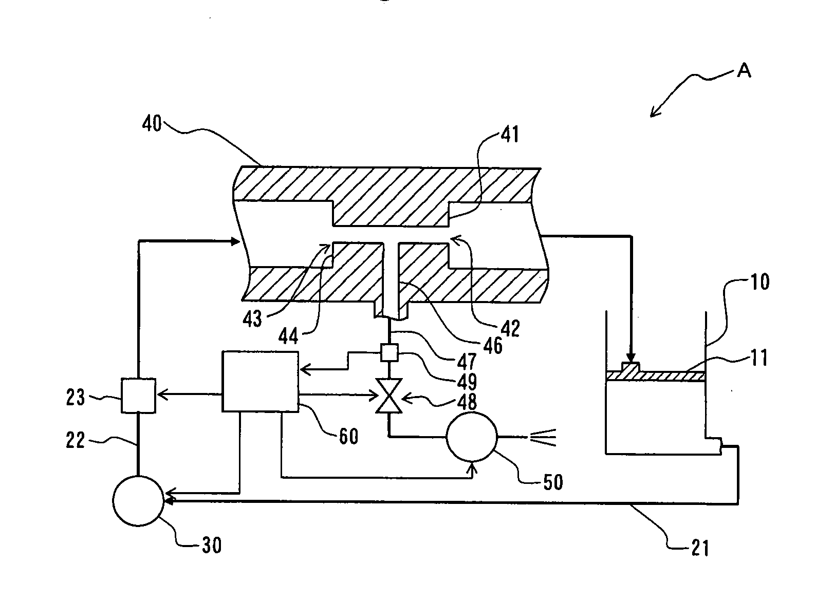
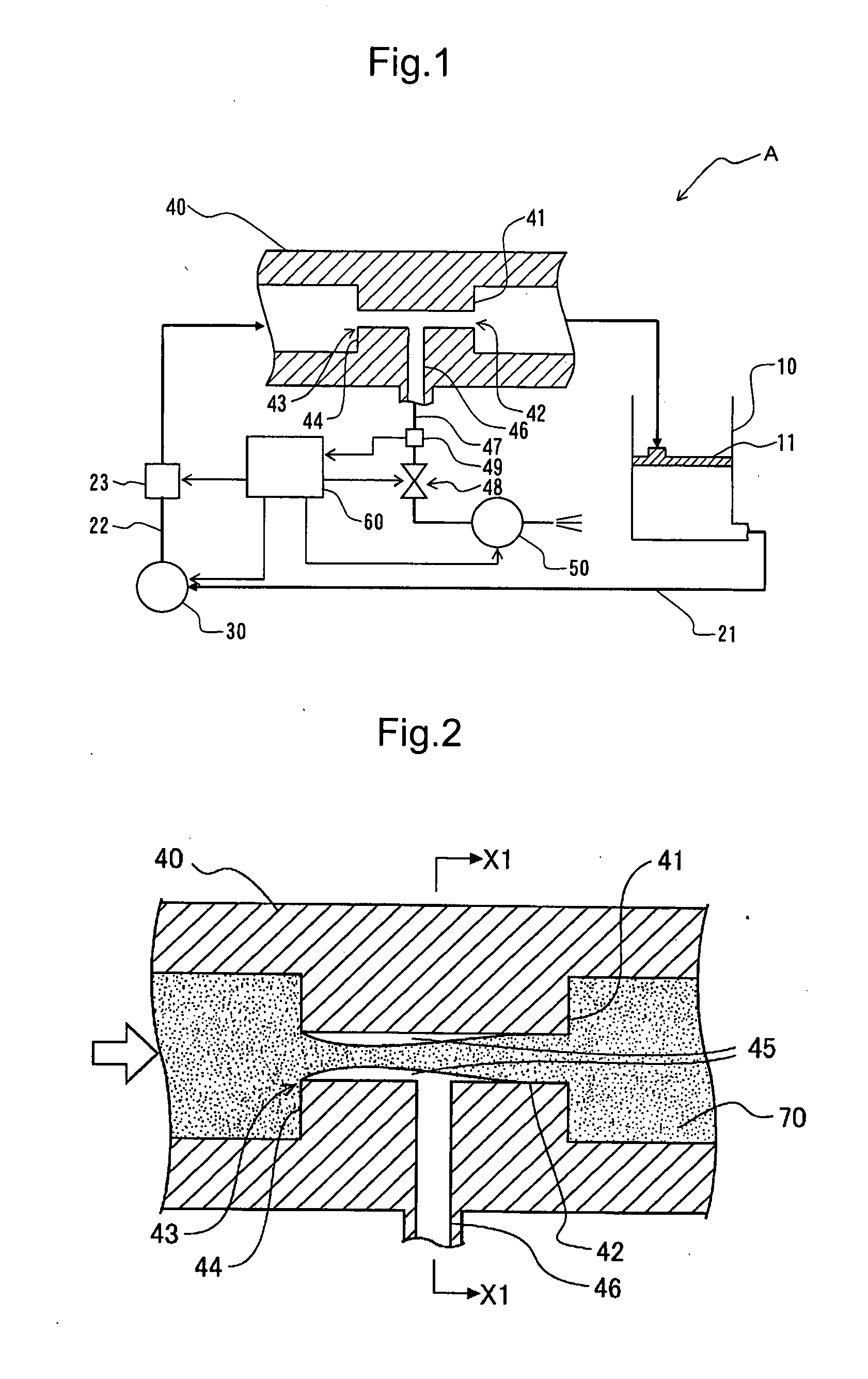
[0033]A deaerator and a deaerating method of the present invention are characterized by performing the deaeration by generating the super cavitation which is one form of the cavitation in the inside of a pipe in which a liquid to be deaerated is supplied.

[0034]That is, when the super cavitation is generated in the inside of the pipe, a cavity having a certain stable shape is formed in the inside of the pipe. Since the inside of the cavity is in an extremely low-pressure state close to the vapor pressure of the liquid, gases are separated into the cavity from the liquid which flows in contact with the cavity whereby the liquid is deaerated.

[0035]Further, a through hole which communicates with the cavity is formed in the pipe, and the gases in the inside of the cavity is sucked and exhausted through the through hole using a suction means such as a vacuum pump or the like thus preventing the establishment of an equilibrium state between the precipitation of gases into the inside of the...


PUM

PropertyMeasurementUnit
Pressureaaaaaaaaaa
Flow rateaaaaaaaaaa

Abstract

The present invention provides a deaerator and a deaerating method which enable the continuous deaeration of a liquid at a low cost. That is, with respect to a pipe which supplies a fluid by a supply means, a rip-out portion which rips out a fluid from an inner peripheral surface of the pipe is provided at a predetermined position in the inside of the pipe, and the fluid is supplied at a predetermined flow rate by a flow control means which adjusts the flow rate of the liquid which is supplied through the pipe so as to form a cavity on a downstream side of the rip-out portion. A through hole which communicates with the cavity is formed in the pipe, and deaeration of the liquid is performed by exhausting gases in the inside of the cavity by suction means such as a vacuum pump via the through hole.

Description

BACKGROUND OF THE INVENTION[0001]The present invention relates to a deaerator and a deaerating method which performs deaeration for removing gaseous components dissolved in a liquid, and more particularly to a deaerator and a deaerating method which can perform the deaeration by continuous processing without using batch processing.[0002]Conventionally, in supplying a liquid using a narrow pipe such as a hydraulic circuit, due to the generation of bubbles in the inside of the pipe, there may arise a trouble in supplying the liquid and hence, the liquid is preliminarily deaerated thus suppressing the generation of the bubbles.[0003]In such a case, usually, the deaeration is performed such that a liquid to be deaerated is stored in the inside of a depressurizing device, and air in the inside of the depressurizing device is exhausted by suction using a vacuum pump or the like thus reducing the pressure in the inside of the depressurizing device. Since it is necessary to hermetically sea...

Claims


Application Information

Patent Timeline
IPC IPC(8): B01D19/00
CPCB01D19/0094B01D19/0036
Inventor WASHIO, SEIICHI
Owner UNIV OKAYAMA
Why Eureka
Try Eureka