
Impact Sensor System For Pedestrian Protection

a sensor system and pedestrian protection technology, applied in contact mechanisms, instruments, force/torque/work measurement apparatus, etc., can solve the problems of causing one type of injury, none of the presently known sensors is able to detect the intensity of the impact and the lateral extent of the impact zon

Active Publication Date: 2008-09-04
IEE INT ELECTRONICS & ENG SA
View PDF6 Cites 6 Cited by
  • Summary
  • Abstract
  • Description
  • Claims
  • Application Information

AI Technical Summary

Benefits of technology

The invention provides an enhanced impact sensor system for pedestrian protection. The system includes a foil-type switching element with multiple active areas that are activated in response to impact. The system uses a foil with a plurality of carrier foils and spacers to create active areas that have different activation thresholds. This allows the system to detect impact with a high degree of accuracy and sensitivity. The system can also include a linear potentiometer that provides more precise information about the location and width of the impact zone. The arrangement of the active areas can be adjusted to optimize the system's response to impact.

Problems solved by technology

When a pedestrian is hit by a motor vehicle, for example a car, one type of injury can be caused by a subsequent collision between the pedestrian's head and the hood of the vehicle.
None of the presently known sensors is able to detect the intensity of the impact and the lateral extent of the impact zone.

Method used


Image

  • Impact Sensor System For Pedestrian Protection
  • Impact Sensor System For Pedestrian Protection
  • Impact Sensor System For Pedestrian Protection

Examples


Embodiment Construction

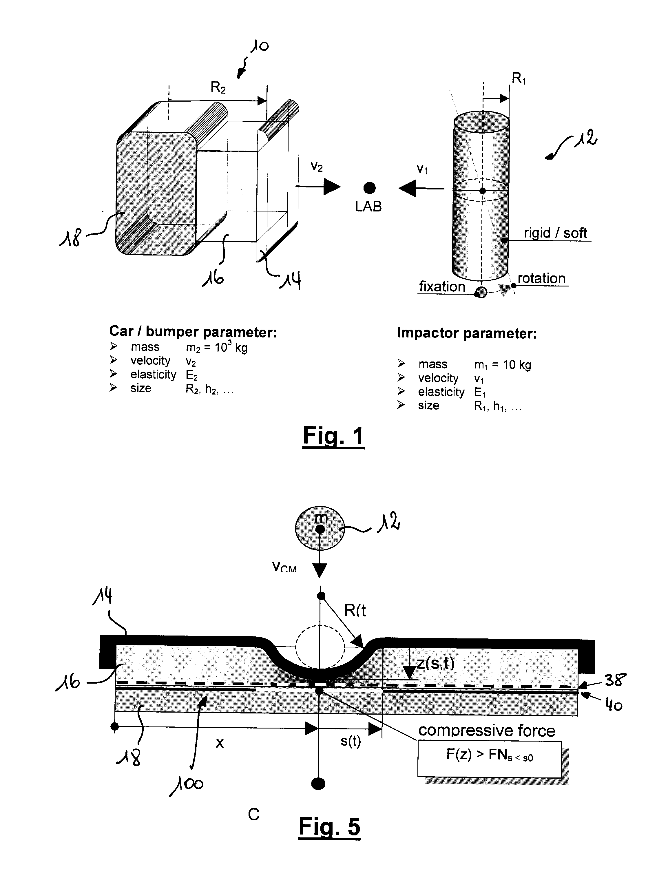
[0028]The present invention relates to an impact sensor system to be integrated in a car bumper environment in order to detect specific parameters (such as impact intensity and impact zone width) relating to an impact between a vehicle and an impacting object so as to enable to classify impact phenomena. Such a sensor system measures simultaneously for a given impact object the position and the lateral distribution of effective force loads versus time. Based on the acquired data an additional algorithm allows a certain classification of the impacting object in order to identify pedestrians and to trigger dedicated safety measures.

[0029]The typical geometry of a car bumper 10 is depicted in FIG. 1, which schematically describes a collision process between a car and an impact object 12. The car bumper 10 consists of an elastic outer skin material 14 backed by an energy absorbing medium 16 and the rigid cross beam 18. In order to identify the impacting object 12 a force sensing system ...


PUM

PropertyMeasurementUnit
activation threshold forcesaaaaaaaaaa
activation threshold forceaaaaaaaaaa
electrical potentialsaaaaaaaaaa

Abstract

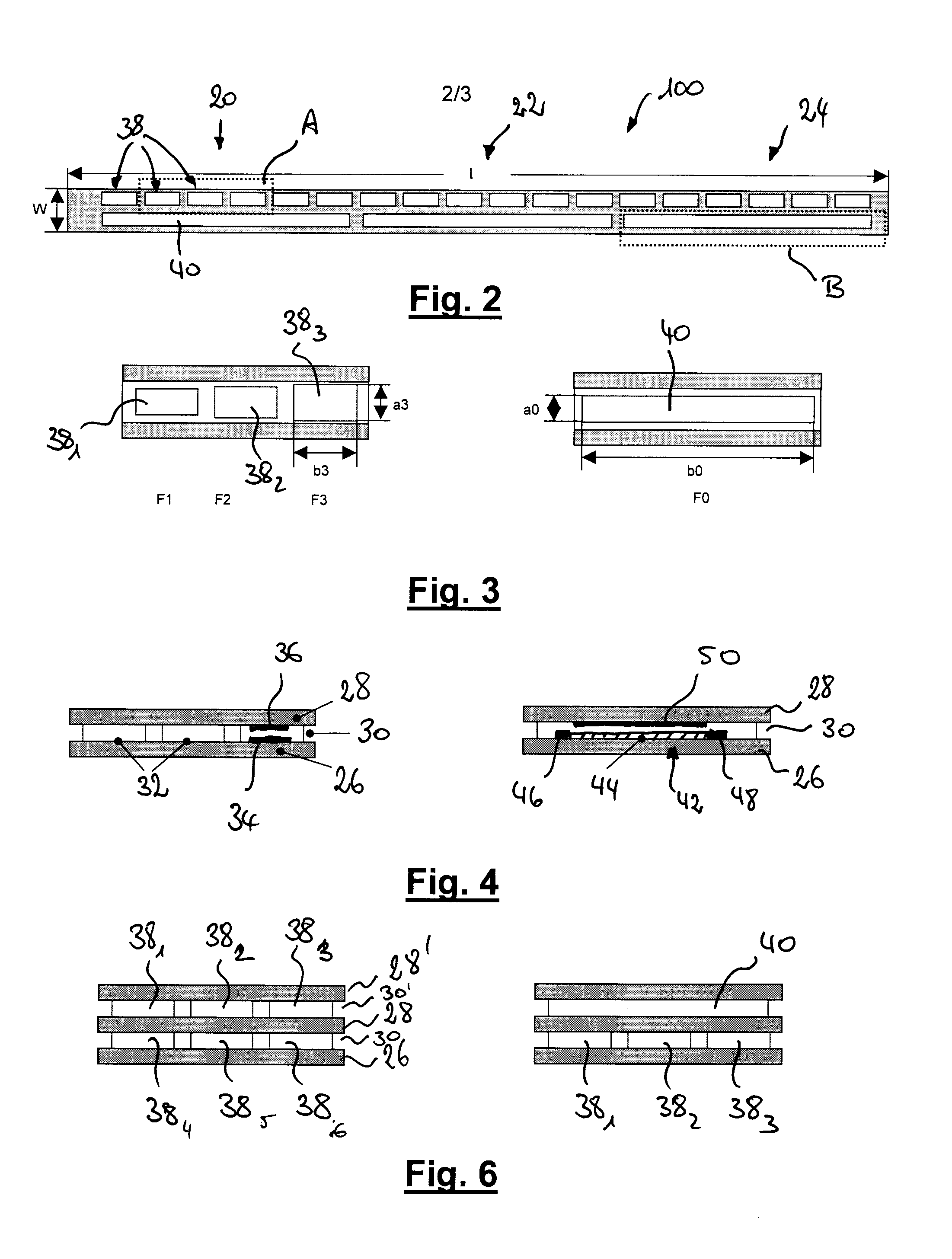
An impact sensor system for pedestrian protection comprises at least one foil-type switching element having a plurality of active areas. The foil-type switching element comprises at least a first carrier foil and a second carrier foil arranged at a certain distance by means of at least one first spacer, wherein said at least one first spacer comprises a plurality of recesses defining at least a first part of said active areas. In each active area, at least two electrode structures are arranged between said first and second carrier foils in such way that in re-sponse to a force acting on the active area of the switching element, the first and second carrier foils are pressed together against the reaction force of the elastic carrier foils and that, above a predetermined activation threshold force, an electrical contact is established between the at least two electrode struc-tures. According to the invention said foil-type switching element is configured such that the activation threshold force of a first group of said plurality of active areas is different from an activation threshold force of a second group of said plurality of active areas.

Description

TECHNICAL FIELD OF THE INVENTION[0001]The present invention generally relates to impact sensor systems for use in triggering operation of a deployable device for protecting a pedestrian hit by the front of a vehicle. The invention more specifically relates to an impact sensor system to be used for the classification of an impact in order to discriminate between impact with a pedestrian and other types of impact.BRIEF DESCRIPTION OF RELATED ART[0002]When a pedestrian is hit by a motor vehicle, for example a car, one type of injury can be caused by a subsequent collision between the pedestrian's head and the hood of the vehicle. In order to minimize these injuries, vehicle manufacturers have started developing safety systems for automotive vehicles, which should help to protect pedestrians in case of a car / pedestrian collision. Such safety systems comprise one or more active systems, for example hood-mounted airbags or energy-absorbing hood panels, which are designed to minimize the i...

Claims


Application Information

Patent Timeline
Patent Type & Authority Applications(United States)
IPC IPC(8): G01L1/06G01P15/135B60R21/01H01B7/10H01H3/14
CPCB60R21/0136H01H3/142G01P15/135B60R21/34
Inventor BIECK, WERNERBOUR, CHRISTIANPETEREIT, ANDREASSCHREINER, MARKUS
Owner IEE INT ELECTRONICS & ENG SA
Learn More