
Airbag fabric diffuser

a fabric diffuser and airbag technology, applied in the direction of pedestrian/occupant safety arrangement, vehicular safety arrangment, vehicle components, etc., can solve the problems of increasing packaging space and high cost of traditional metal diffuser systems, and achieve the effect of improving airbag performance and facilitating the even deployment or inflation of airbags

Inactive Publication Date: 2005-09-20
TAKATA RESTRAINT SYST
View PDF26 Cites 57 Cited by
  • Summary
  • Abstract
  • Description
  • Claims
  • Application Information

AI Technical Summary

Benefits of technology

[0002]As the automobile has developed, so have methods of ensuring passenger safety. Several methods of safety restraint systems have emerged during this development, including the airbag. Since the introduction of the airbag various degrees of implementing it have emerged including use in protecting passengers from side impact scenarios. To achieve this, vehicle designers have placed airbag systems in a number of locations including passenger seats, vehicle doors and vehicle roof frames. Various methods of improving airbag performance have also been developed. One example, pertinent to the present invention, is the use of a cylindrical metal diffuser that facilitates even deployment or inflation of the airbag.
[0003]It is an object of the present invention to make a significant improvement over side impact airbag systems through implementation of an improved diffuser system. Although effective, traditional metal diffusing systems often tend to be relatively expensive and may require an increased amount of packaging space. This has an overall effect of limiting the areas wherein diffused airbag systems can be implemented. The present invention replaces the traditional metal diffuser systems with a fabric diffuser. The fabric diffuser offers the same performance as the traditional diffusers, however, it boasts distinct advantages. Initially, a fabric diffuser is both lightweight and cost effective. Manufacture of a fabric diffuser is also less complicated than that of a metal diffuser. A more significant advantage is that fabric diffuser systems in accordance with the present invention have improved packaging characteristics over traditional metal diffusers and can disperse gas rearwardly into the cushion. A fabric diffuser, in contrast to a metal diffuser, can be tightly folded with the overall airbag in its initial packaging. As a result, more options are open to designers in locating airbag systems.
[0004]An airbag of the present invention comprises a sewn outer shell, and a diffuser system, to include a perforated fabric diffuser and a perforated cushion deflector, disposed within the sewn outer shell. As a result of the advantages described above, the airbag can be inconspicuously packaged in the upper trim running a distance along the front and rear passenger windows. The sewn outer shell is preferably sewn in such a way as to form individual cell areas. In a preferred embodiment, the diffuser incorporates a series of openings along its edge that are located at an area generally above each of the individual cells. Upon deployment of the airbag, the inflation gas initially inflates the diffuser system. The diffuser system then channels the gas to the individual cells, causing the airbag to be evenly inflated. Such a system offers a significant degree of protection for both front and rear passengers. The present airbag is particularly useful as a head side airbag, but not however thereby limited.

Problems solved by technology

Although effective, traditional metal diffusing systems often tend to be relatively expensive and may require an increased amount of packaging space.
The present airbag is particularly useful as a head side airbag, but not however thereby limited.

Method used


Image

  • Airbag fabric diffuser
  • Airbag fabric diffuser
  • Airbag fabric diffuser

Examples


Embodiment Construction

[0011]The present invention is primarily directed at airbag or vehicle occupant protection systems and more specifically to improving the adaptability and performance of such systems through the use of a diffuser system.

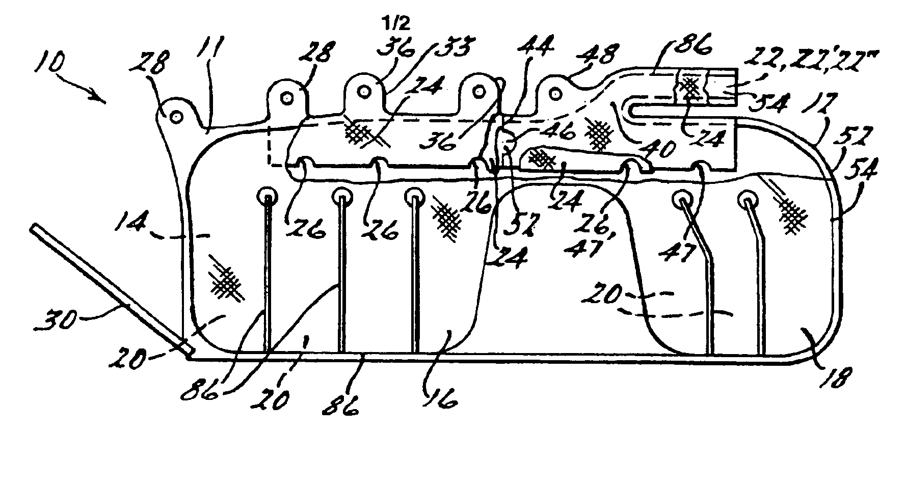
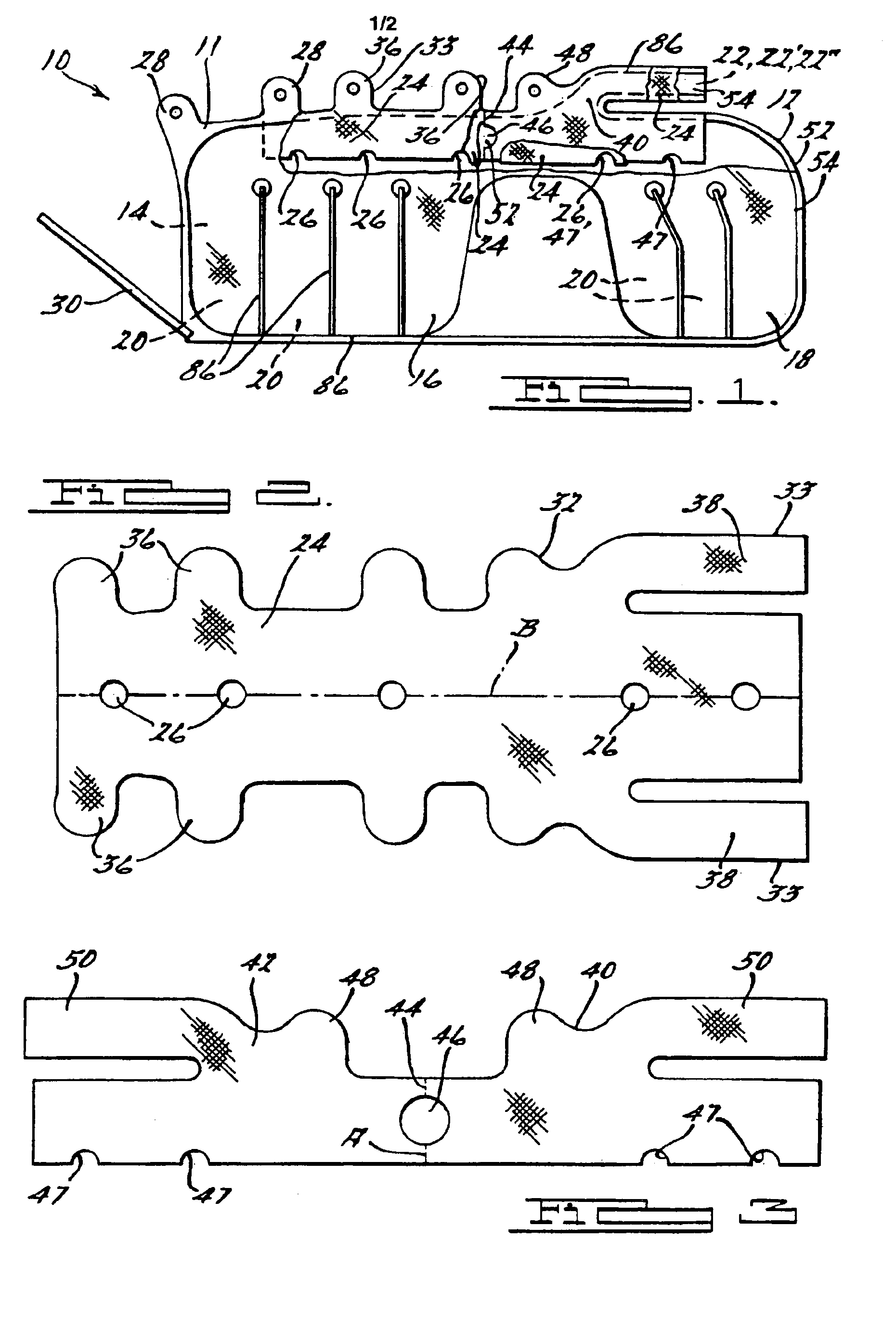
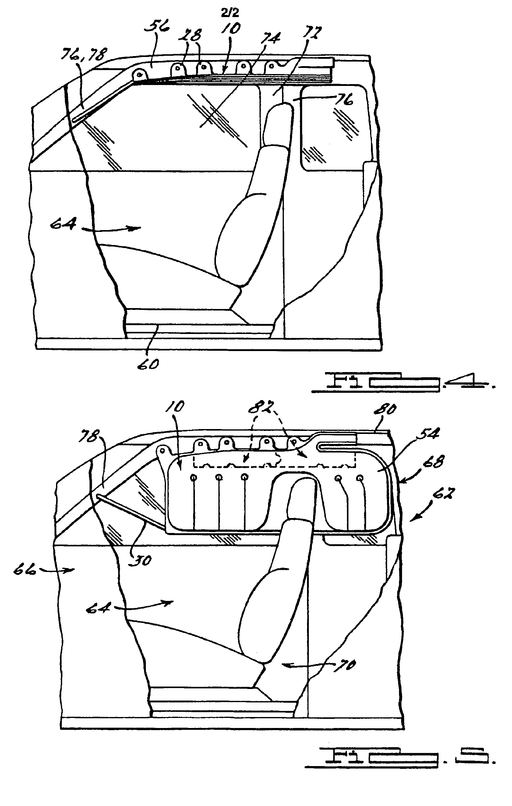
[0012]With reference to FIG. 1, the side view of a head side airbag 10 (also referred to as a cushion) is displayed. An outer shell 12 is sewn in such a manner as to form an interior 14 and two portions, 16 and 18, each having a plurality of individual cells 20, and an inlet 22. Internal to the sewn outer shell is a fabric or cloth diffuser 24. The fabric or cloth diffuser 24 has a series of openings 26 along its edges and in a preferred embodiment, may also include an inlet or gas entry orifice 22′ in lieu of an inlet on the airbag. The outer shell 12 is constructed in such a manner as to form a first plurality of tab portions 28 which are used to attach the airbag 10 to a vehicle (best shown in FIGS. 4 and 5). Additionally, a strap 30 is sewn to a corner of the air...


PUM


Abstract

A perforated fabric diffuser and perforated cushion deflector are sewn inside an outer shell, thus forming a diffuser system within an airbag. The diffuser contains a plurality of openings along a folded edge. The deflector contains a wall defining at least one orifice for attenuating gas flow upon airbag activation. The airbag contains an inlet that fluidly communicates with the deflector and diffuser upon airbag activation. The outer shell is preferably sewn in such a manner as to maintain a plurality of individual cell areas. The fabric diffuser system is disposed within the outer shell such that the diffuser openings are positioned generally over the individual cells. During deployment, the diffuser system thereby functions to facilitate substantially even inflation throughout the airbag.

Description

FIELD OF THE INVENTION[0001]The present invention relates generally to safety restraint systems using airbags and particularly to an airbag containing a perforated cloth diffuser and a perforated cushion deflector. A preferred configuration facilitates even deployment of a head side airbag for protection of vehicle occupants from side impact.BACKGROUND AND SUMMARY OF THE INVENTION[0002]As the automobile has developed, so have methods of ensuring passenger safety. Several methods of safety restraint systems have emerged during this development, including the airbag. Since the introduction of the airbag various degrees of implementing it have emerged including use in protecting passengers from side impact scenarios. To achieve this, vehicle designers have placed airbag systems in a number of locations including passenger seats, vehicle doors and vehicle roof frames. Various methods of improving airbag performance have also been developed. One example, pertinent to the present inventio...

Claims


Application Information

Patent Timeline
IPC IPC(8): B60R21/16B60R21/26B60R21/20B60R21/213B60R21/231B60R21/233
CPCB60R21/232B60R21/233B60R21/2338B60R21/2346B60R21/213B60R2021/23316B60R2021/23386
Inventor MAERTENS, PAUL G.
Owner TAKATA RESTRAINT SYST
Learn More