
Apparatus for positioning anchor bolts and method of using same

a technology of anchor bolts and anchor bolts, which is applied in the direction of bulkheads/piles, soil preservation, artificial islands, etc., can solve the problems of insufficient depth in the rock complex to provide reliable consolidating forces, failure of anchor tendon, and difficulty in manual insertion of tendon in boreholes, etc., to achieve the effect of simplifying the positioning or insertion of reinforcing tendons

Active Publication Date: 2008-08-28
DSI UNDERGROUND CANADA LTD SOUTERRAIN DSI CANADA LTEE
View PDF9 Cites 0 Cited by
  • Summary
  • Abstract
  • Description
  • Claims
  • Application Information

AI Technical Summary

Benefits of technology

[0008]To at least partially overcome some of the disadvantages associated with prior art wall and mine roof support systems, the present invention provides an apparatus and method for the simplified positioning or insertion of reinforcing tendons within drill holes formed in a rock complex.
[0009]Another object of the invention is to provide a tendon positioning apparatus which is adapted for use in either conventional concrete wall, rock wall or mine roof support systems, and which enables a single user to quickly and easily achieve full seating of a reinforcing tendon at the desired location relative to the rock face.

Problems solved by technology

The applicant has appreciated that the length of conventional reinforcing tendons used in mine roof support systems, and the requirement of seating the tendon into elongate drill holes against the resistive forces of both multiple unruptured resin / grout cartridges, and the viscous forces of the released resin, makes the manual insertion of the tendon in the bore hole both difficult and time consuming.
Furthermore, if the tendon is not fully seated in the bore hole and spun before the anchoring resin sets, the tendon may not be positioned at a sufficient depth in the rock complex to provide reliable consolidating forces.
This in turn may result in either the failure of the anchor tendon, or in a worst case scenario rock wall failure.
The requirement of providing a separate apparatus, however, to position reinforcing tendons has not achieved widespread acceptance in the mining industry, as a result of the increased costs and inconvenience associated with providing and transporting separate drilling and positioning tools to a mine work site.
In addition, in underground mining operations dust, dirt and mining debris frequently results in the jamming of the drive wheels often binding the reinforcing tendon therein, and necessitating frequent repair and / or replacement.

Method used


Image

  • Apparatus for positioning anchor bolts and method of using same
  • Apparatus for positioning anchor bolts and method of using same
  • Apparatus for positioning anchor bolts and method of using same

Examples


Embodiment Construction

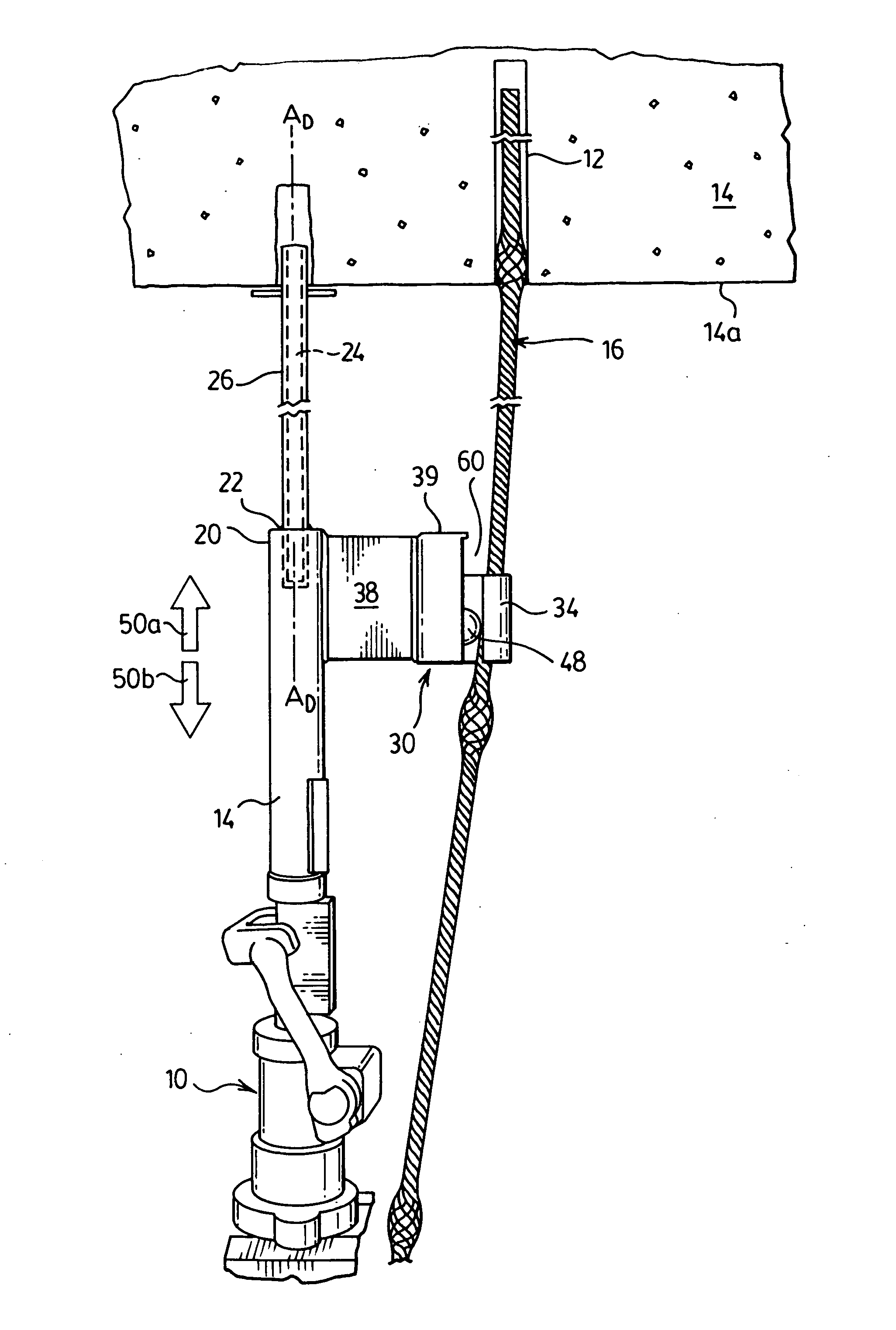
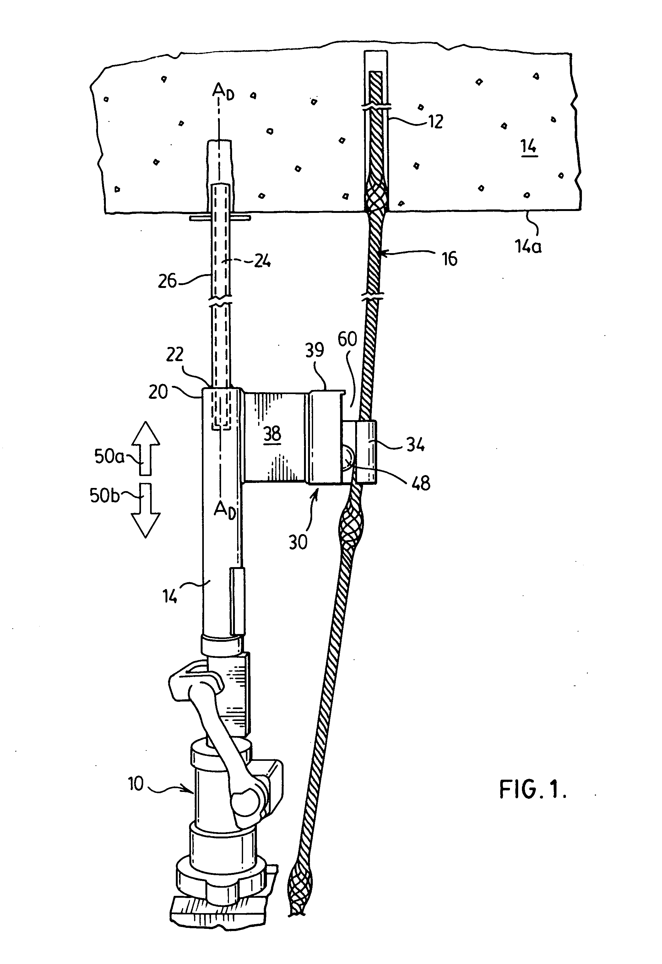
[0041]The present invention relates to a stoper 10 for use in the installation of mine roof support systems. As will be described, the stoper 10 is operable by a single user to initially form a drill hole 12 in a rock roof complex 14, and thereafter position and seat a bulged cable bolt 16 in the drill hole 12 as a reinforcing tendon for use in compressing and consolidating rock forces. The stoper 10 is sized to be manually held by a single individual operator at an intended site of use. The stoper 10 includes an elongated pneumatically operable air-leg 18 which in use is positioned in a generally vertical orientation and then reciprocally moved in the forward and rearward directions of arrows 50a,50b towards and away from the rock complex 14. The nose end 20 of the air-leg 18 is provided with a chuck 22 which is configured to matingly receive therein a longitudinally elongated drill steel 24. Although not essential, a removable steel sleeve 26 is preferably provided for selective p...


PUM


Abstract

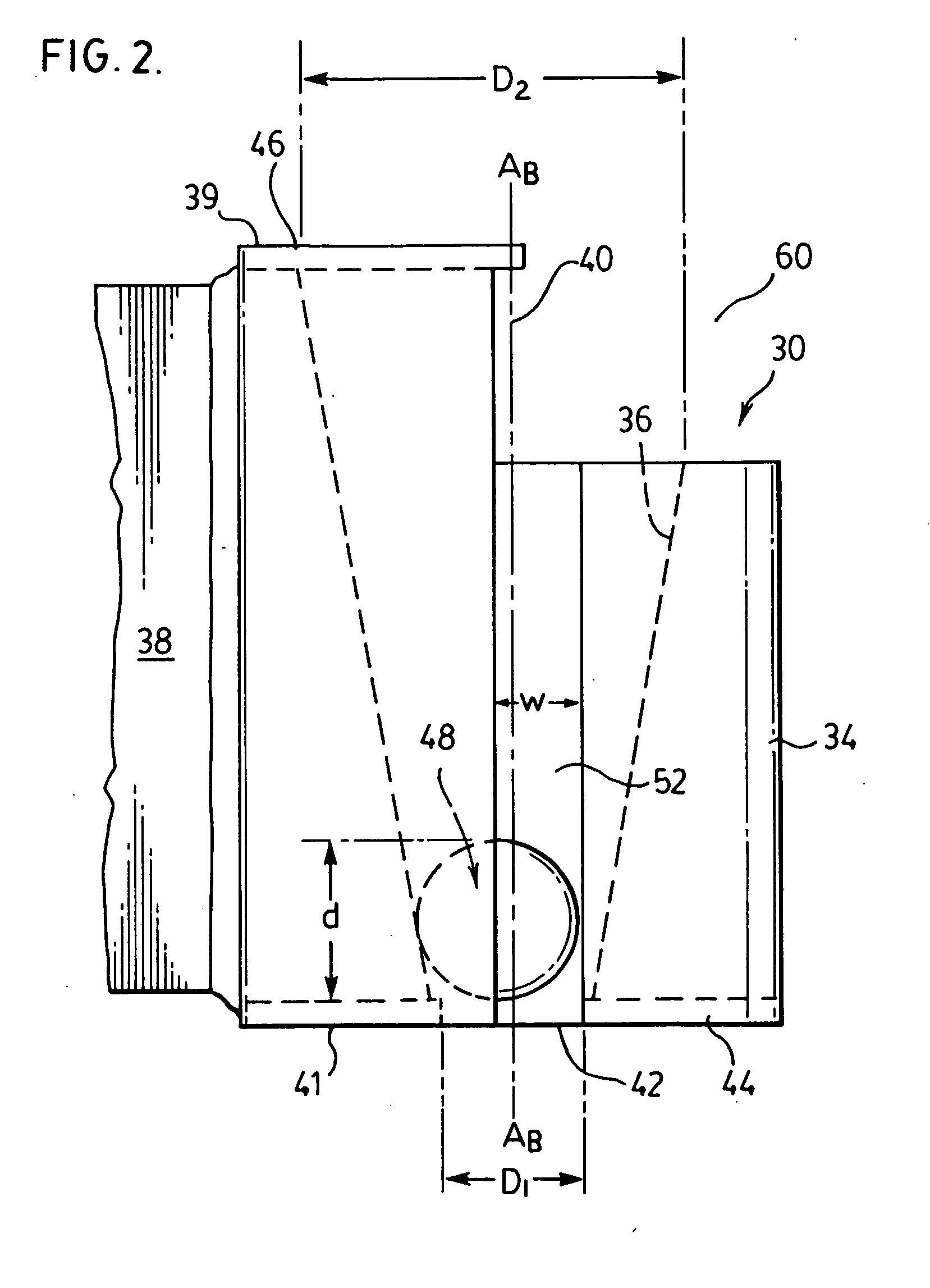
An apparatus for positioning a reinforcing tendon into a drill hole formed rock face including a body portion having a bore extending axially therethrough. The bore has a dimension selected to allow limited sliding movement of the tendon therethrough and includes a portion which tapers inwardly from a forward outfeed end towards a rearward or infeed end. A wedging member is movably provided in the bore. Movement of the wedging member towards the rearward end of the body results in its frictional engagement with the tendon to restrict its withdrawal from the body relative to the infeed end, whereas movement of the wedging member relative to the bore towards the outfeed end results in its disengagement from the tendon allowing it to be repositioned forwardly relative to the body. A drive is further provided to reciprocally move the body relative to the rock face.

Description

SCOPE OF THE INVENTION[0001]The present invention relates to an apparatus for positioning anchor bolts or reinforcing tendons used in mine and wall support systems, and more particularly an apparatus which is operable to urge the reinforcing tendon into a drill hole formed in a rock face to a seated position where it may be secured in place by mechanical couplers, resins and / or grouts.BACKGROUND OF THE INVENTION[0002]In concrete wall, mine roof and rock wall support systems (hereinafter collectively referred to as mine roof support systems), it is known to stabilize ground forces by first embedding longitudinally elongated reinforcing tendons in bore or drill holes drilled into the rock complex, and then tightening a nut against the wall or rock face to compress and consolidate rock forces.[0003]To form drill holes, pneumatically operated boring tools, such as a hand-held or ground supported stoper or jackleg is used. The boring tools are provided with a reciprocally movable air-leg...

Claims


Application Information

Patent Timeline
IPC IPC(8): E02D5/00
CPCE21D20/006
Inventor GASCON, RHEAL
Owner DSI UNDERGROUND CANADA LTD SOUTERRAIN DSI CANADA LTEE
Learn More