
Imaging apparatus and reproducing apparatus

a technology of reproducing apparatus and video contents, which is applied in the field of imaging apparatus, can solve the problems of reproducing apparatuses, copyright piracy becomes a bigger problem, and dvd production of pirated media, and achieve the effect of preventing surreptitious recording of video contents and preventing reproduction of surreptitiously recorded video contents

Inactive Publication Date: 2008-08-28
JVC KENWOOD CORP A CORP OF JAPAN
View PDF5 Cites 92 Cited by
  • Summary
  • Abstract
  • Description
  • Claims
  • Application Information

AI Technical Summary

Benefits of technology

The present invention provides an imaging apparatus and a reproducing apparatus that can detect and prevent surreptitious recording of video content, such as movies, without requiring any additional equipment arrangement or addition. The imaging apparatus includes an average luminance calculating unit and a detecting unit that calculates a ratio of maximum to minimum average luminance of the image and determines if it is equal to or higher than a predetermined value to determine if the image is of a movie. The reproducing apparatus includes an average luminance calculating unit and a detecting unit that calculates a ratio of maximum to minimum average luminance of the image and determines if it is equal to or higher than a predetermined value to determine if the image is of a movie. The apparatuses can then send a warning signal or message to alert the user that the image may be of a movie. This invention helps to protect against unauthorized recording of movies and other video content.

Problems solved by technology

There is a problem in that video contents such as a movie is surreptitiously recorded without authorization at a theater and then pirated media such as DVDs are produced.
Such copyright piracy becomes a bigger problem with advancement of high-resolution imaging apparatuses for HD (High Definition) televisions.
Another problem lies in reproducing apparatuses.

Method used


Image

  • Imaging apparatus and reproducing apparatus
  • Imaging apparatus and reproducing apparatus
  • Imaging apparatus and reproducing apparatus

Examples


first embodiment

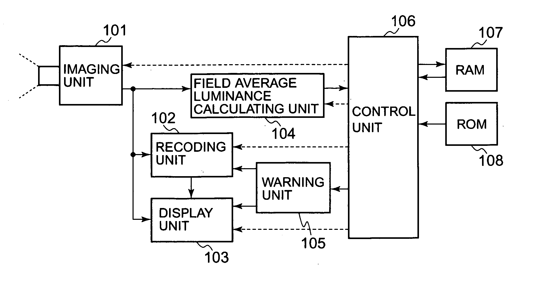
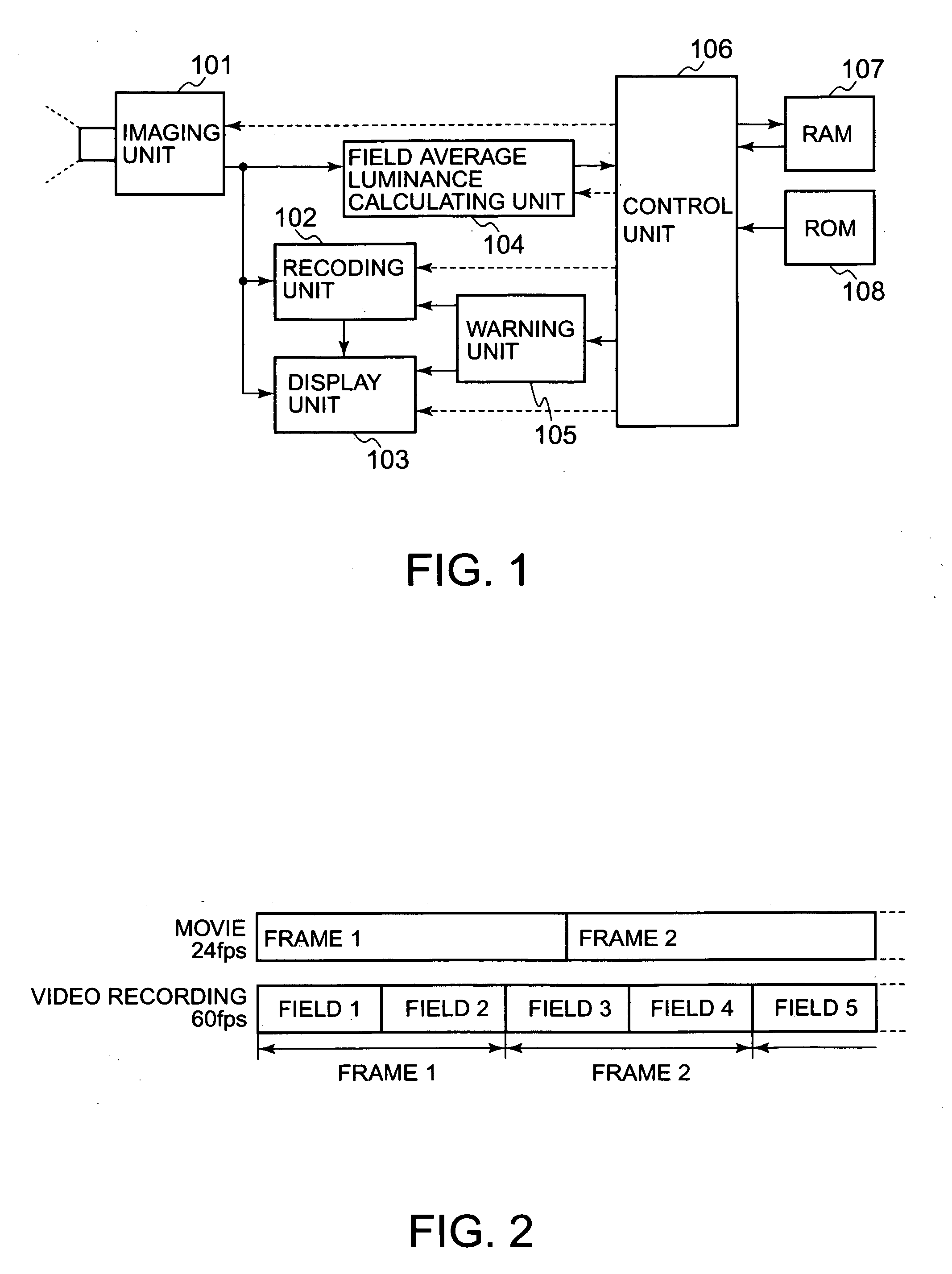
[0046]Disclosed first with reference to FIG. 1 is an imaging apparatus that is a first embodiment of the present invention.

[0047]The imaging apparatus shown in FIG. 1 is provided with an imaging unit 101, a recording unit 102, a display unit 103, a field average luminance calculating unit 104, a warning unit 105, a control unit 106, a RAM 107, and a ROM 108.

[0048]The imaging unit 101 takes images of an object and converts them into electrical signals. The unit 101 also has optical functions, such as, lens focusing to the object. The recording unit 102 records the images on storage media, such as, a magnetic tape, an HDD, a magnetic disc, a memory, and an optical disc. Moreover, the unit 102 erases the recorded data under control by the control unit 106. The display unit 103 displays images taken by the imaging unit 101, information necessary for imaging such as time, or images recorded by the recording unit 102. The field average luminance calculating unit 104 calculates field avera...

second embodiment

[0086]Disclosed next with reference to FIG. 8 is an imaging apparatus that is a second embodiment of the present invention.

[0087]The imaging apparatus shown in FIG. 8 is provided with an imaging unit 2101, a recording unit 2102, a display unit 2103, an average luminance calculating unit 2104, a warning unit 2105, a control unit 2106, a RAM 2107, and a ROM 2108.

[0088]The imaging unit 2101 takes images of an object and converts them into electrical signals. The unit 2101 also has optical functions, such as, lens focusing to the object. The recording unit 2102 records the images on storage media, such as, a magnetic tape, an HDD, a magnetic disc, a memory, and an optical disc. Moreover, the unit 2102 erases the recorded data under control by the control unit 2106. The display unit 2103 displays images taken by the imaging unit 2101, information necessary for imaging such as time, or images recorded by the recording unit 2102. The average luminance calculating unit 2104 calculates avera...

third embodiment

[0135]Disclosed first with reference to FIG. 17 is an imaging apparatus that is a third embodiment of the present invention.

[0136]The imaging apparatus shown in FIG. 17 is provided with an imaging unit 3101, a recording unit 3102, a display unit 3103, an average luminance calculating unit 3104, a warning unit 3105, a control unit 3106, a RAM 3107, and a ROM 3108.

[0137]The imaging unit 3101 is equipped with: an imaging device 3101a for taking images of an object; and a visible-light luminance measuring device 3101b for measuring the luminance of light from the object, for which the images are being taken, through lenses (not shown) and converting the measured luminance into electrical signals. The imaging unit 3101 converts the images taken by the imaging device 3101a into electrical signals. The unit 3101 also has optical functions, such as, lens focusing to the object.

[0138]The recording unit 3102 records the images on storage media, such as, a magnetic tape, an HDD, a magnetic dis...


PUM


Abstract

An imaging unit takes an image and converts the image into a video signal. A display unit displays the image carried the by the video signal. An average luminance calculating unit calculates average luminance of the image per first predetermined period. A detecting unit calculates a ratio of maximum to minimum average luminance of the average luminance over a second predetermined period that is an integer multiple of the first predetermined period and determines whether the ratio is equal to or higher than a predetermined value. The detecting unit determines that the image taken by the imaging unit is an image of a movie projected onto a screen when it is determined that the ratio is equal to or higher than the predetermined value. A warning unit sends a warning signal to the display unit when the detecting unit determines that the image taken by the imaging unit is the image of the movie. The display unit then displays an warning message carried by the warning signal with the image.

Description

CROSS-REFERENCE TO RELATED APPLICATIONS[0001]This application is based on and claims the benefit of priority from the prior Japanese Patent Application Nos. 2007-049117 filed on Feb. 28, 2007, 2007-049118 filed on Feb. 28, 2007, 2007-093161 filed on Mar. 30, 2007, and 2007-340173 filed on Dec. 28, 2007, the entire contents of which is incorporated herein by reference.BACKGROUND OF THE INVENTION[0002]The present invention relates to an imaging apparatus equipped with a function capable of preventing surreptitious recording of video contents such as a movie at a theater and a reproducing apparatus equipped with a function capable of preventing reproduction of such surreptitiously recorded video contents.[0003]There is a problem in that video contents such as a movie is surreptitiously recorded without authorization at a theater and then pirated media such as DVDs are produced. Such copyright piracy becomes a bigger problem with advancement of high-resolution imaging apparatuses for HD...

Claims


Application Information

Patent Timeline
Patent Type & Authority Applications(United States)
IPC IPC(8): H04N5/913
CPCH04N5/77H04N5/782H04N2005/91392H04N5/907H04N5/913H04N5/85
Inventor KOBAYASHI, KAZUHIDE
Owner JVC KENWOOD CORP A CORP OF JAPAN
Learn More