
System for Sensing a Physical Property in a Plurality of Scanning Positions

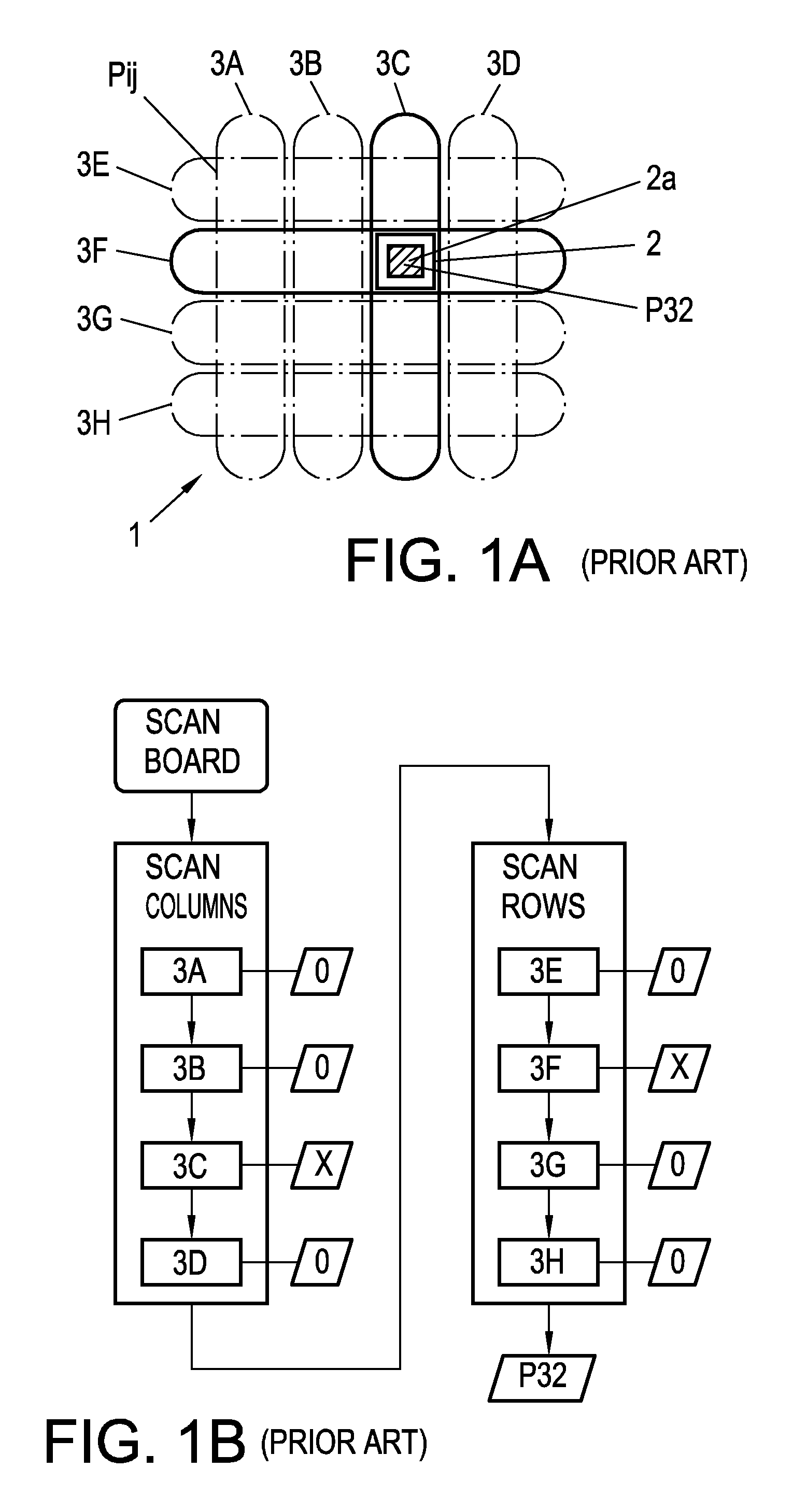
a technology of scanning position and physical property, applied in the field of system for sensing physical property, can solve the problems of increasing the production cost of the known system, prohibiting the production cost, and prohibiting the production cost, and achieves the effect of reducing the amount of wiring of the sensing system, high resolution, and quick determination

Inactive Publication Date: 2008-08-28
NXP BV
View PDF7 Cites 4 Cited by
  • Summary
  • Abstract
  • Description
  • Claims
  • Application Information

AI Technical Summary

Benefits of technology

[0013]The invention provides the advantage that the number of sensors to be used to unambiguously sense and localize a given physical property in scanning positions is considerably reduced compared with known systems. The reduced number of sensors requires less wiring from the sensors to detectors, therefore reduces the production cost and renders it possible to design smaller systems. Finally, the localization speed is considerably accelerated since fewer localization steps have to be carried out to determine the location of the physical property in given scanning positions, which scanning positions are arranged in a line, a plane, or a space.
[0020]These measures provide the advantage of a maximum utilization of the unique pattern of sensing regions, resulting in a very low or even no redundancy in respect of sensors and wiring lines between the sensors and detectors.
[0021]The physical property to be sensed comprises identity codes of RFID transponders of objects, and the sensors are configured as antennas for reading the identity codes of the RFID transponders. Such a sensing system is highly flexible at low production cost, since antennas for RFID transponders (tags) can be produced cheaply with arbitrary shapes and aspect ratios, so that varying shapes of scanning positions can be sensed within one sensing system according to the invention, offering the possibility to adapt the system to almost any conceivable needs without appreciable extra cost. For instance, the antennas may be formed by bending of wires or by applying electrically conductive pastes or inks onto a carrier.
[0026]If the detector of the present sensing system is adapted to allocate the sensing signals as discrete numbers to the respective digits of the position code, a wider variety of sensors can be used in embodiments of the invention, comprising not only digital sensors that deliver a binary TRUE / FALSE result of their sensing, but also analog sensors whose analog sensing signals are converted by the detector into discrete numbers which are entered into the respective digits of the position codes, so that the sensing result can be evaluated with high resolution.
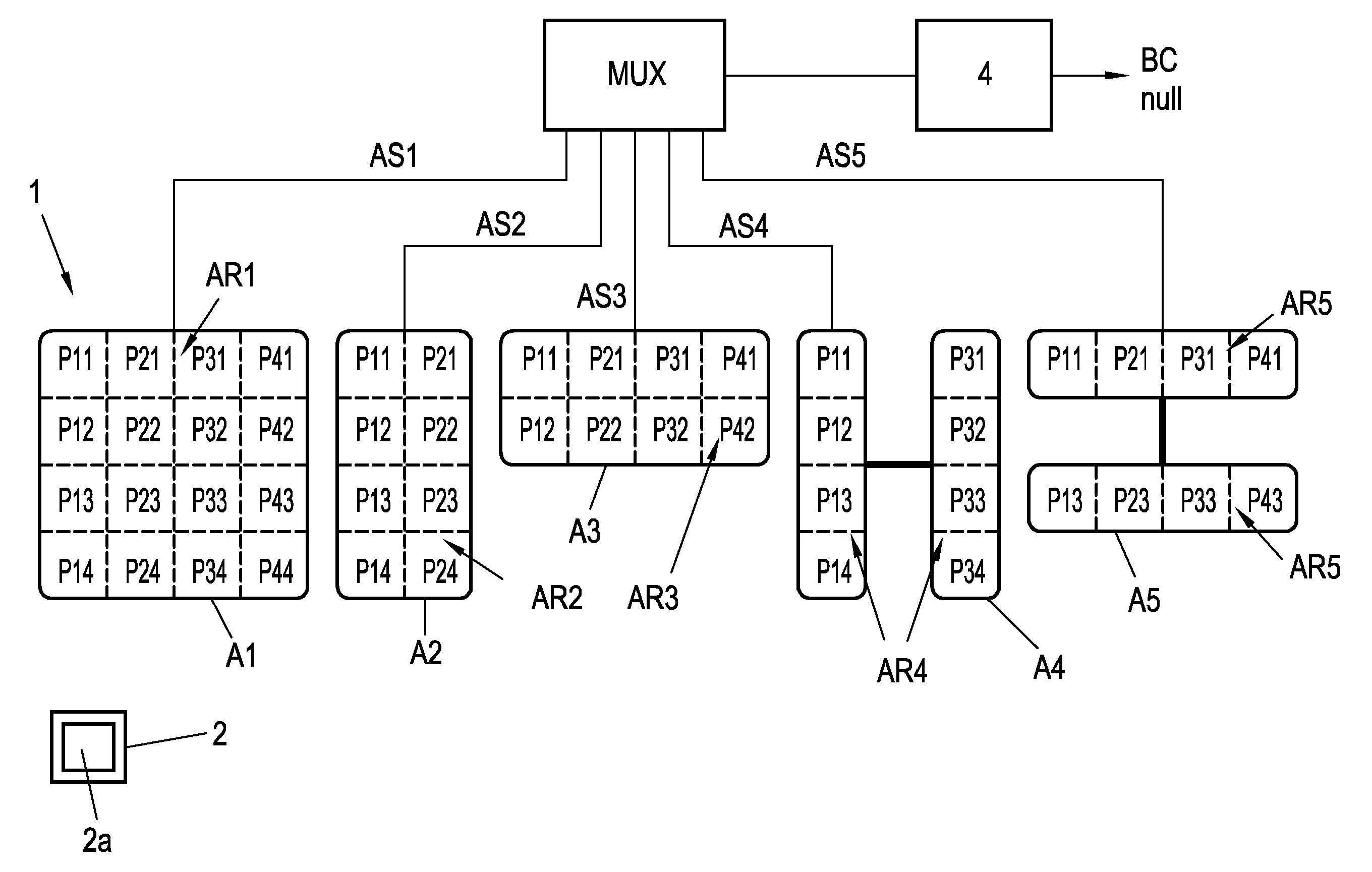
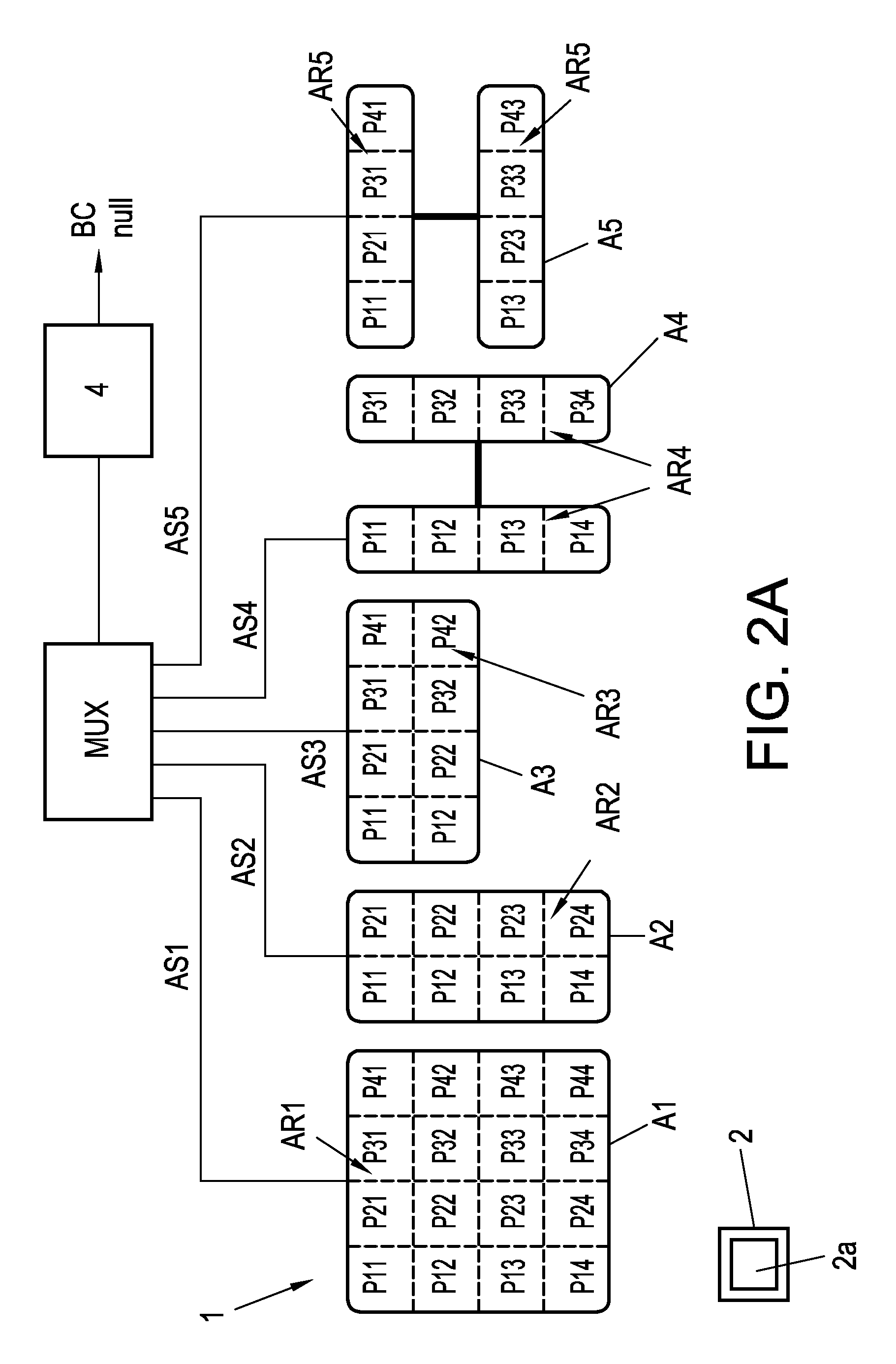
[0027]To reduce the amount of wiring of the sensing system considerably, the sensing signals may be fed to a multiplexer whose output is fed to the detector. The sensors may thus very well be located away from the detector.
[0028]In a further embodiment of the present sensing system, a sensor with a sensing region is provided that sweeps the entirety of scanning positions. These measures provide the advantage that prior to carrying out an exact localization operation for predefined physical properties a very quick determination can be made whether the property is present in any scanning position at all. This can result in an accelerated processing speed. The aspects defined above and further aspects of the invention are apparent from the exemplary embodiments to be described hereinafter and are explained with reference to these exemplary embodiments

Problems solved by technology

With a multitude of detectors, however, the cost is prohibitive.
The known sensing systems were thus found to have the disadvantage that a multitude of sensors is necessary that may result in a prohibitive production cost.
The sensors need to be connected to multiple detectors which further increases the production cost of the known systems.
Finally, the high number of necessary scanning steps slows down the localization speed.

Method used


Image

  • System for Sensing a Physical Property in a Plurality of Scanning Positions
  • System for Sensing a Physical Property in a Plurality of Scanning Positions
  • System for Sensing a Physical Property in a Plurality of Scanning Positions

Examples


Embodiment Construction

[0041]FIG. 2A shows a game board 1 that is divided into sixteen scanning positions P11-P44 (generally Pcolumn-row) on which an object 2 with specific properties can be placed. The scanning positions P11-P44 are arranged in a matrix with four rows and four columns. The board 1 includes a sensing system according to the invention sensing for a predefined physical property. In the present embodiment, the sensing system is adapted as a system for localizing the object 2 that has the predefined physical property within one of the scanning positions P11-P44. For example, the object 2 may be configured as a token with a built-in RFID tag 2a. Each scanning position is identified by a unique binary position code BC (see FIG. 2B), as will be explained below. The system for localizing the object 2 comprises a plurality of sensors A1-A5, which in this embodiment are configured as antennas for reading the RFID tag 2a. Strictly speaking the sensors A1-A5 are configured as loop antennas having sen...


PUM


Abstract

A system for sensing a physical property allocated to scanning positions (P1-P5, P11-P44, Pijk) comprises sensors (A1-A5, B) adapted to sense the physical property within sensing regions (AR1-AR5, BR1-BR2, C1-C3, D1-D3, E1-E3, F1-F4, G1-G3, H1-H4), wherein the sensing regions (AR1-AR5, BR1-BR2, C1-C3, D1-D3, E1-E3, F1-F4, G1-G3, H1-H4) are arranged such that each of them sweeps at least one scanning position (P1-P5, P11-P44, Pijk) and sensing regions (AR1-AR5, BR1-BR2, C1-C3, D1-D3, E1-E3, F1-F4, G1-G3, H1-H4) are superposed on one another at least at one scanning position (P1-P5, P11-P44, Pijk), so that each scanning position is swept by a unique pattern of sensing regions (AR1-AR5, BR1-BR2, C1-C3, D1-D3, E1-E3, F1-F4, G1-G3, H1-H4), wherein the following condition is fulfilled:log2(n)≦i<x·n1 / x withi . . . number of sensing regionsn . . . number of scanning positionsx . . . number of spatial dimensions in which the arrangement of scanning positions extend.

Description

FIELD OF THE INVENTION[0001]The invention relates to a system for sensing a physical property allocated to scanning positions, comprising sensors adapted to sense the physical property within sensing regions that are arranged such that each of said regions sweeps at least one scanning position, the sensing regions being superposed on one another at least in one scanning position, so that each scanning position is swept by a unique pattern of sensing regions.BACKGROUND OF THE INVENTION[0002]Sensing systems that comprise sensors with sensing regions are commonly known, wherein the sensing regions of these sensors are arranged in a row-column configuration. For instance, objects with built-in RFID tags can be cheaply localized in specific positions on a shelf or at specific terminals of a robotic delivery system, which shelves or terminals are swept by an arrangement of antennas configured in rows and columns. Each specific position is defined by the intersection of one row antenna wit...

Claims


Application Information

Patent Timeline
IPC IPC(8): G06K7/01
CPCG01S5/02G01S13/878G06K7/0008G06K2017/0045G06K7/10346G06K7/10356G06K7/10079
Inventor FONTIJN, WILHELMUS FRANCISCUSDIJKSTRA, EELCO
Owner NXP BV
Learn More